MagShake: Reducing
magnetic bead loss one shake at a time
In biology, a common method for sample detection/ purification typically uses specially functionalized magnetic particles, known as magnetic beads. Magnetic beads are now the gold standard for detection/ purification and are commonly used to detect or separate and purify DNA, RNA, cells, and proteins.
However, magnetic beads are expensive, costing hundreds to thousands of dollars for a small sample. Purification processes involve multiple wash steps to remove contaminants such as cell debris. During these washes, it is common to experience magnetic bead loss during each wash. The amount of bead and target product yield loss depends on several factors, including magnetic bead type, concentration, volume, microplate type, magnetic separation plate strength, shape, and location, etc.
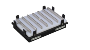
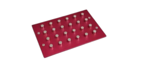
At V&P Scientific, we offer a variety of Magnetic Bead Separation Plates that effectively and efficiently separate your magnetic beads to minimize bead loss. Moreover, our most recent development VP 333A – the MagShake, further reduces the number of individual outlier magnetic bead particles that could potentially be lost during waste removal steps. MagShake utilizes two vibration motors with adjustable shake amplitude, which provides a customizable oscillatory/vibration movement to facilitate tighter magnetic bead pellets.
To help illustrate this, we conducted a magnetic bead separation test using 2 different types of magnetic beads, Ampure and Magnesil and on two different V&P magnetic separation plates:
200 μL of each bead sample at 10mg/ml in distilled water was pipetted into a 96-well 1 mL round-bottom NUNC microplate (Catalog number NUNC 260252). 50 μL of 0.05% tween tris buffered saline solution was also added to each well.
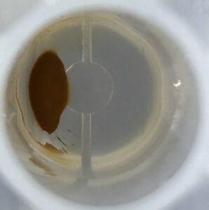
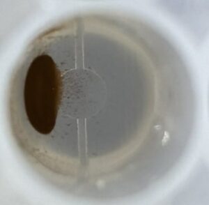
Each magnetic bead plate was placed on the corresponding magnetic separation block for 2 minutes to allow the beads to separate. After separation, the MagShake was then turned on for 1 minute at 50% intensity, and the results are as follows:
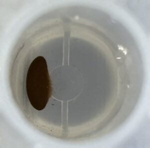
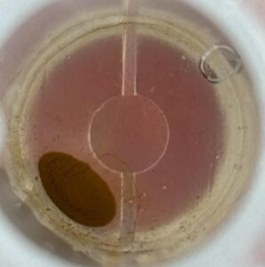
VP 771MWZM-1 with Ampure Beads

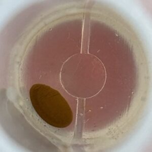
VP 771MWZM-1 with Magnesil Beads
VP 771LA-1ZS with Ampure Beads
VP 771LA-1ZS with Magnesil Beads
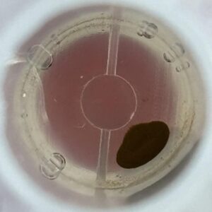
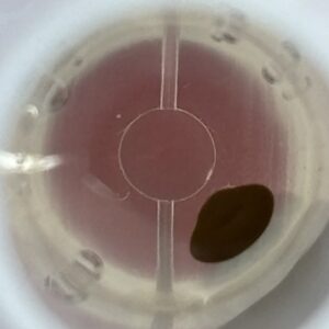
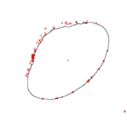
The raw before and after pictures visually depict the aggregation of magnetic beads post-shake. The before photos have more stray outlier beads dispersed along the bottom of the well around the main bead pellet. The after photos show a clearer, more defined pellet with fewer outlier beads. Visually, the MagShake created enough disruption to cause the stray outlier beads to converge toward the main magnetic bead pellet, tightening the overall pellet and reducing the number of free beads. By creating a tighter pellet, fewer beads will be lost during the supernatant removal step, which happens multiple times for most wash protocols.
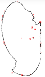
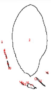
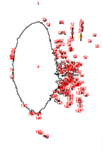
To better understand and quantify the bead aggregation results, we used ImageJ image analysis software’s particle analysis function to identify the number of independent particles in each picture.
ImageJ particle analyzed images:
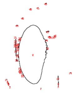
VP 771MWZM-1 with Ampure Beads
| Before | After |
 |  |
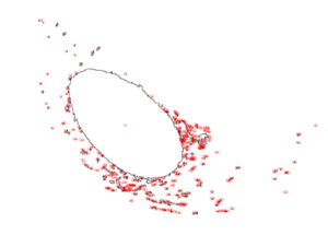
VP 771MWZM-1 with Magnesil Beads
| Before | After |
 |  |
VP 771LA-1ZS with Ampure Beads
| Before | After |
 | 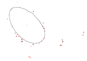 |
VP 771LA-1ZS with Magnesil Beads
| Before | After |
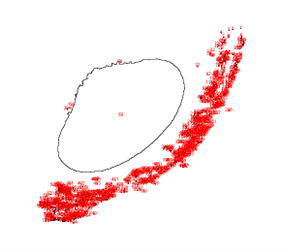 |  |
AMPURE BEADS | UNIQUE PARTICLE COUNT | UNIQUE PARTICLE COUNT |
| BEFORE | AFTER |
VP 771MWZM-1 | 28 | 18 |
VP 771LA-1ZS | 316 | 40 |
|
|
|
MAGNASIL BEADS |
|
|
| BEFORE | AFTER |
VP 771MWZM-1 | 149 | 48 |
VP 771LA-1ZS | 794 | 48 |
Upon running the magnetic bead images through ImageJ particle analysis software, we see that the number of identifiable independent outlier magnetic bead particles decreased anywhere from 35.7% to 94% after just 1 minute of MagShake operation at 50% power. This means that the MagShake vibration causes the beads to aggregate into larger and fewer bunches, which will hold tighter than stray outlier beads due to neighboring magnetic effects, and result in less chance of bead loss.
The MagShake device helps improve magnetic bead separation by providing enough vibration motion to cause outlier beads to travel towards the magnetic field source without causing the well contents to mix. Better magnetic bead separation minimizes the loss of expensive magnetic beads, and results in higher target yields. While our tests demonstrate that unique particle count decreased significantly, results may vary depending on magnetic bead type, bead concentration, magnetic plate strength, shape and location, shake settings, microplate well type, well surface texture.