Magnetic Poles: Alternating or Not Alternating, That Is The Question
At V&P Scientific, we carry a series of Magnetic Bead Separation Blocks with a custom-designed bar magnet for separating larger volumes, such as those in deep well microplates (DWPs). In this “M” series of bar magnet blocks, we have many to choose from where the number of bar magnets is different depending on the number of wells in the microplate and if the pellet needs to be divided into the two sides of the well or remain on only one side. The focus of this blog will be the 7-bar Magnetic Bead Separation Block shown below in figure 1 and its use with the larger volumes in DWPs.

“M” Series Magnetic Bead Separation Blocks
| Part Number | Number of Magnets | Deep Well Microplate | Mag Bead Pellet Position |
|---|---|---|---|
| VP 771MAZM-1 | 4 bars | 6, 24, 48 | One side of the well |
| VP 771MCWZM-1 | 6 bars | 96 | One side of the well |
| VP 771MWZM-1 | 7 bars | 24, 48, 96 | Two opposing sides of the well (24, 48) One side of the well (96) |
| VP 771MDWZM-1 | 13 bars | 96 | Two opposing sides of the well |
North Pole Up: All of these “M” series Magnetic Bead Separation Blocks are assembled with all of the bar magnets positioned north pole up. As we often do, we will create or modify one of our research tools based on a customer request (so don’t be shy about talking to us). In the case of the 7-bar magnet block VP 771MWZM-1 and a 48-deep well microplate with rectangular wells, they asked if we had tried to alternate the poles: north, south, north, south, etc.
Alternating North and South Poles: We found that by alternating the poles of the magnets in the 7 bar magnetic bead separation block (VP 771MWZM-1-ALT), the separation of beads in a 48 well deep well plate with rectangular wells (10 ml per well) was significantly improved. This was characterized by keeping the beads off of the bottom of the well and more tightly collected next to the well’s vertical wall (see figure 4).

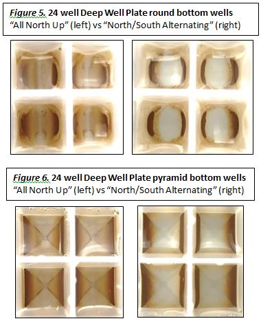
24 and 48 Well Deep Well Microplates: Recently a customer asked about a 24 well magnetic bead separation block. She also was using 48 well DWPs. Remembering a past customer who ordered a custom version of the 7 bar magnetic bead separation block VP 771MWZM-1-ALT with the alternating magnetic poles had also used a 48 well DWP, I thought that maybe the 24 well DWP would work as well. A test with Beckman’s Agencourt GenFind magnetic beads and two different 24 well DWPs, one with round bottom wells (figure 5) and the other pyramid ones (figure 6), also resulted in improved separation with VP 771MWZM-1-ALT. Beads that were encroaching on the lowest point of the well with the “all north up” magnets, were pulled up to the sides of the wells where the wall goes vertical when separated with the “north/south alternating” magnets. The proof is in the pictures!
96 Well Deep Well Microplates: Why stop with 24 and 48 well DWPs? What about 96 Well Deep Well Plates? A similar difference is seen for separation in a 96 well plate (Figure 7 below), where having the magnetic poles alternating creates a a tighter collection of beads to the side.

Alternating Magnetic Poles are The Answer.
At least it is the answer for large volumes of magnetic beads in deep well microplates when using V&P’s 7-bar magnet block! So when you are doing magnetic bead assays, be they protein or nucleic acid isolations, and you have a large volume of sample in a twenty-four, forty-eight, or ninety-six well plate, the VP 771MWZM-1-ALT is the magnetic separation block to use.
And The Rest Of The Story:
To visualize the magnetic field lines, we have a single well plate filled with iron filings that we place on top of the magnet separation block we want to examine. The iron filings will align with the magnetic lines of flux as they go from the north pole to the south pole.
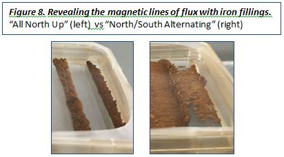
In Figure 8 you can see two bar magnets (of the 7-bar separation block VP 771MWZM-1) with north poles up in the photo on the left. The filings are all “lined up” along each bar magnet’s north pole edge. That is because the magnetic lines of flux are vertical as they extend from the poles. Since the south poles are on the opposite side of the bar magnet, the magnetic lines of flux have to reach up high and bend around to the opposite ends of the entire separation block to find the south poles. This contrasts the photo on the right in Figure 8, which shows the filings connecting the alternating pole magnets of a 7-bar separation block VP 771MWM-1-ALT. Here, you can see the filings follow the magnetic lines of flux as they reach toward each other over the gap between the magnets. This happens because the north and south poles are closer to each other, and the magnetic lines of flux can go right over! How does this relate to the magnetic bead separation tests I showed above? Imagine a 24 well positioned in that gap between the two bar magnets. If the iron filings are visualizing the magnetic “power” that is supposed to pull the beads over to the bars at the sides of the wells, then it is easy to see which magnetic pole configuration would work best!