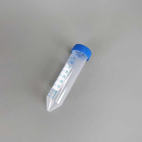
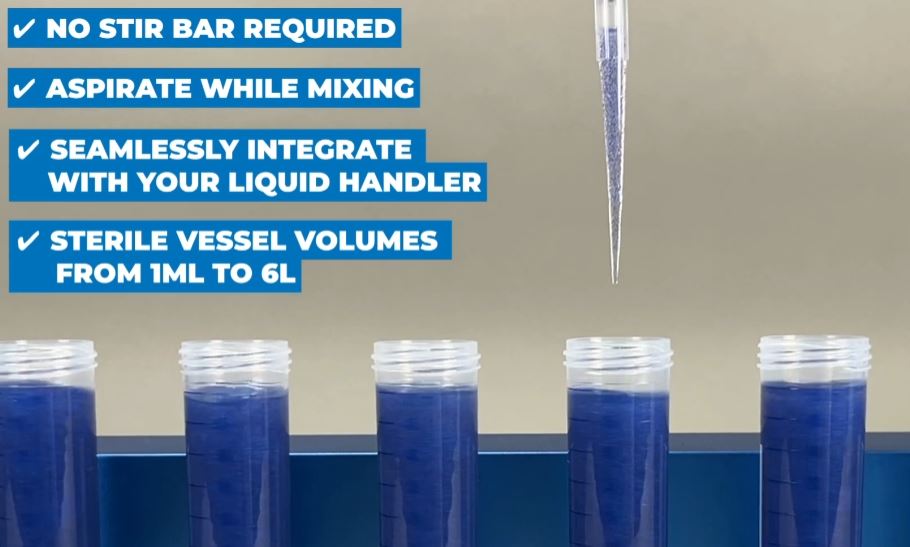
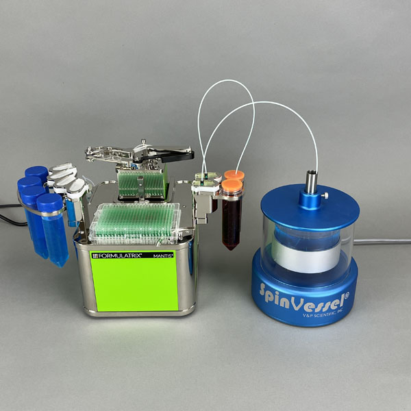
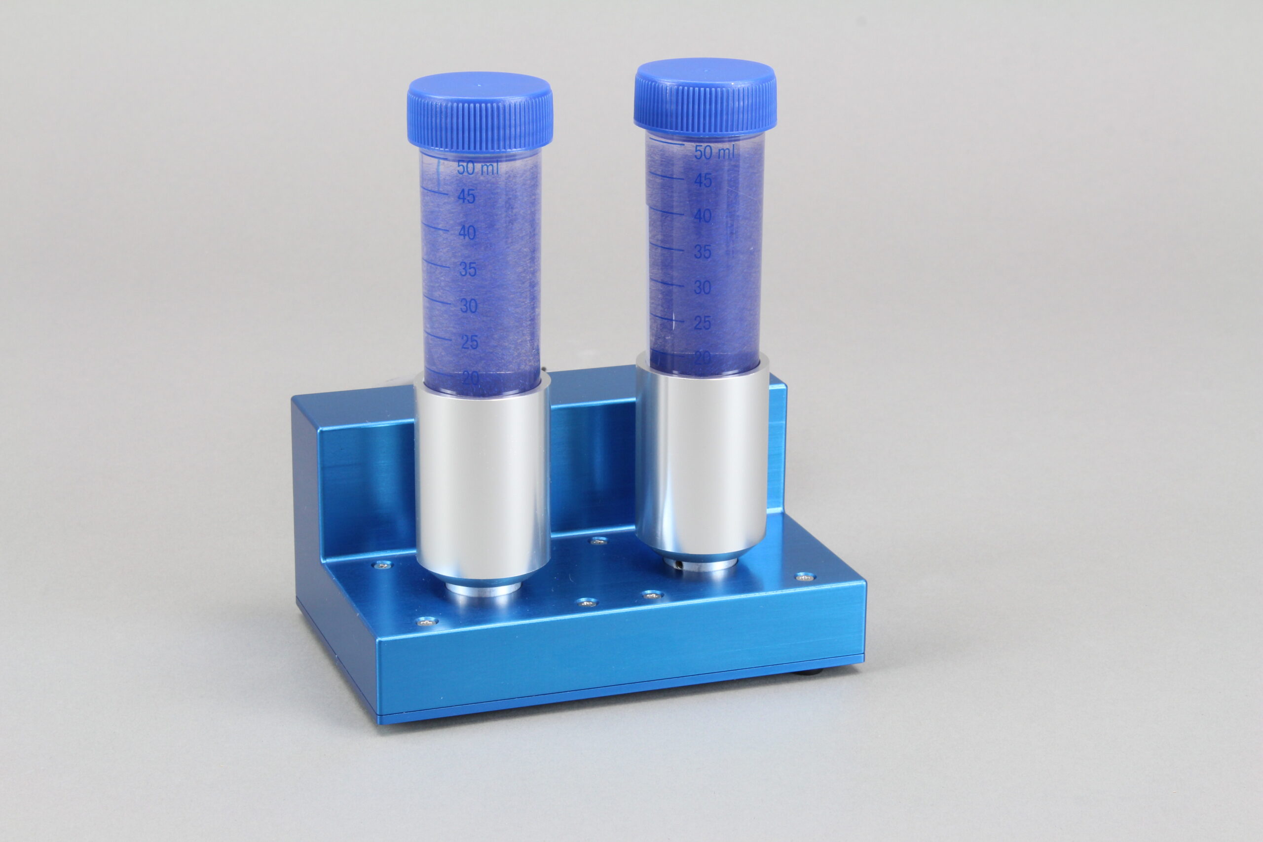
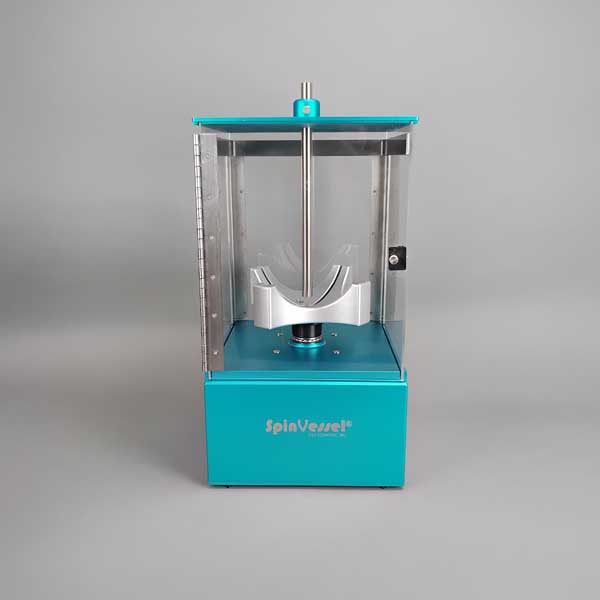
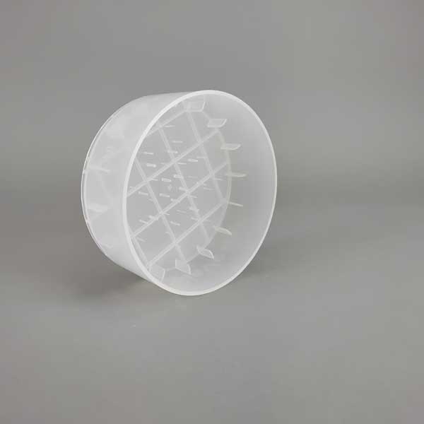
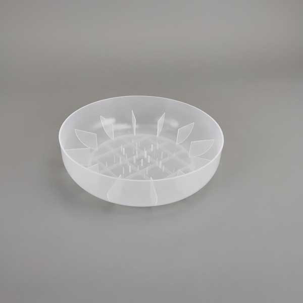
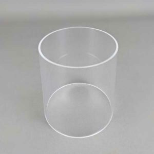
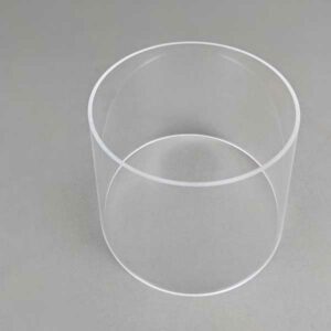
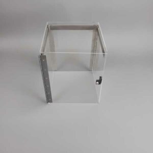
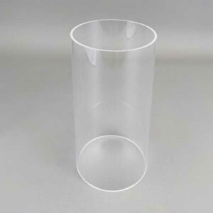
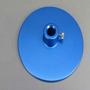
The SpinVessel® provides a completely new method (using Pulsed Radial Flow) to mix and uniformly suspend particulates in a liquid on robotic liquid handlers and robotic reagent dispensers. It can also do this without damaging the particulates or killing fragile cells as conventional methods often do. See our SLAS Technology Paper that validates the gentle and uniform suspension of cultured cells. V&P Scientific, Inc. is very honored and humbled to receive the SLAS 2020 New Product Award for the SpinVessel®.
Not only are we able to mix and suspend particulates without a magnetic stir bar, but we are able to mix/suspend while rotating around a fixed position on a robotic deck. Thus, facilitating robotic pipetting; a robot friendly feature that no other mixing/suspending machine possesses.
Through Pulsed Radial Flow (US Patent #11,623,188, European Patent #3887049), we achieve homogenous mixing and uniform suspension of particulates. The key is reversing the direction of our radially oriented fins and projections of our patented SpinVessels®.
Our method of mixing and suspension is achieved by integrating radially oriented fins and projections in a vessel and pairing the vessel to a device that alternately reverses the vessel’s spin direction to generate a circular pulsed radial fluid flow. The flow path starts at the bottom of the vessel, where the fluid and particulates are pushed to the sidewalls of the vessel. As the fluid and particle mixture strikes the sidewall, the side fins guide the fluid flow up the vessel, thus generating lift along the vessel walls. The fluid flow loop is completed by the mixture flowing down the center of the vessel due to gravity and the nature of radial flow.
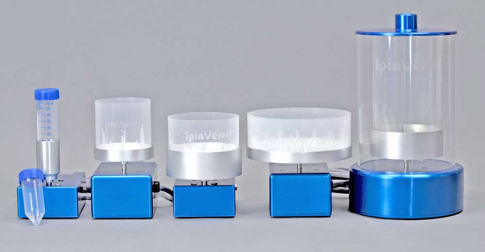
Mixes in both Large and Small Volumes. Ranges from 25ml up to 6L.
Extensive SpinVessel® data showing both vertical and horizontal homogeneous particulate suspension was published in SLAS Technology with volumes ranging from 50ml to 1.2L.
We can suspend Glass Beads, Magnetic Beads, Resin Beads, Blood, Cells, Bacteria, Virus Particles, Vesicles, Liposomes, Micelles, DNA, RNA, Proteins, Antigens, Ligands, Analytes.
SpinVessel® data demonstrating 5 different particulates (HEK cells, CHO cells, Cytodex Microcarrier beads, Magnetic beads, and Silica beads) being uniformly suspended horizontally and vertically in different SpinVessel®s is also presented in the SLAS Technology paper.
Pulsed Radial Flow redirects lateral motion into vertical flow up the vessel wall without producing opposing sheer forces. With the SpinVessel®, no cell membranes are caught between two moving surfaces (Stir Elements). See abstract from SLAS Technology paper.
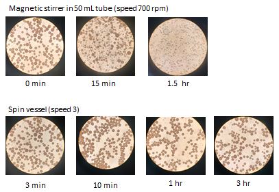
We maintain cell viability (HEK cells and CHO cells) even after 2 hours of continuous SpinVessel® stirring because we don’t use Stir Elements, which can grind cell membranes between the container and the stir bar. With the SpinVessel®, no cell membranes are caught between two moving surfaces.
See Tables 1, 2, and 3 and the text of page 504 of the SLAS Technology Paper.
Strategically placed projections allow for pipetting on multiple formats and can be used with Robotic Equipment. No Stir Bar means lower Dead-Volume as the pipette tips and siphon hoses can reach the very bottom of the SpinVessel®.
Uniformly Suspend Particulates: Glass Beads, Magnetic Beads, Resin Beads, Blood, Cells, Bacteria, Virus Particles, Vesicles, Liposomes, Micelles, DNA, RNA, Proteins, Antigens, Ligands, Analytes
Compatible with both Liquid Handling Robots as well as Reagent Dispensing Robots to Facilitate Automated Assays
Dissolve Solids Blend Viscous Solutions Blend Slurries Oxygenate Cell Culture Media
We did some testing with dispensing our beads and we’re very happy with the results.
“We’re dispensing 1mL of bead solution into a 96 well, 2mL block plate. The beads settled out in the plate after just a couple of minutes and we can see that the amount of beads per well is much more consistent than we were able to get by any other method.”
Showing 1–12 of 46 results
Pin | Description | nl Transferred | CV% | |
---|---|---|---|---|
0.229 mm diameter (FP9) | Total Pin | Uncoated | 7.41 | 2.4 |
Hydrophobic | 7.46 | 5.4 | ||
0.229 mm diameter (FP9) | Hanging Drop | Uncoated | N/A | N/A |
Hydrophobic | 2.09 | 3.8 | ||
0.457 mm diameter (FP1) | Total Pin | Uncoated | 33.48 | 3.2 |
Hydrophobic | 28.17 | 7.5 | ||
0.457 mm diameter (FP1) | Hanging Drop | Uncoated | 16.96 | 4.5 |
Hydrophobic | 8.51 | 0.8 | ||
0.787 mm diameter (FP3) | Total Pin | Uncoated | 87.32 | 3.9 |
Hydrophobic | 77.4 | 3.9 | ||
0.787 mm diameter (FP3) | Hanging Drop | Uncoated | 48.77 | 1.2 |
Hydrophobic | 43.05 | 9.4 | ||
1.19 mm diameter (VP 409 & VP 386) | Total Pin | Uncoated | 247.22 | 2.8 |
Hydrophobic | 192.67 | 2.6 | ||
1.19 mm diameter (VP 409 & VP 386) | Hanging Drop | Uncoated | 76.35 | 1.6 |
Hydrophobic | 108.4 | 2.8 | ||
1.58 mm diameter (VP 408 & VP 384) | Total Pin | Uncoated | 273.5 | 4.6 |
Hydrophobic | 259.25 | 3.1 | ||
1.58 mm diameter (VP 408 & VP 384) | Hanging Drop | Uncoated | 201.93 | 5 |
Hydrophobic | 170.04 | 7.5 |
Transfer Of Horseradish Peroxidase In Tris Buffered Saline With Pin Tools
Coating pins will reduce the total amount of liquid transferred and also reduce the amount of non-specific binding to the stainless-steel pins. If the substance you are transferring has high non-specific binding this will be an important factor in selecting your pins.
Pin | Description | nl Transferred | CV% | |
---|---|---|---|---|
0.229 mm diameter (FP9) | Total Pin | Uncoated | 7.41 | 2.4 |
Hydrophobic | 7.46 | 5.4 | ||
0.229 mm diameter (FP9) | Hanging Drop | Uncoated | N/A | N/A |
Hydrophobic | 2.09 | 3.8 | ||
0.457 mm diameter (FP1) | Total Pin | Uncoated | 33.48 | 3.2 |
Hydrophobic | 28.17 | 7.5 | ||
0.457 mm diameter (FP1) | Hanging Drop | Uncoated | 16.96 | 4.5 |
Hydrophobic | 8.51 | 0.8 | ||
0.787 mm diameter (FP3) | Total Pin | Uncoated | 87.32 | 3.9 |
Hydrophobic | 77.4 | 3.9 | ||
0.787 mm diameter (FP3) | Hanging Drop | Uncoated | 48.77 | 1.2 |
Hydrophobic | 43.05 | 9.4 | ||
1.19 mm diameter (VP 409 & VP 386) | Total Pin | Uncoated | 247.22 | 2.8 |
Hydrophobic | 192.67 | 2.6 | ||
1.19 mm diameter (VP 409 & VP 386) | Hanging Drop | Uncoated | 76.35 | 1.6 |
Hydrophobic | 108.4 | 2.8 | ||
1.58 mm diameter (VP 408 & VP 384) | Total Pin | Uncoated | 273.5 | 4.6 |
Hydrophobic | 259.25 | 3.1 | ||
1.58 mm diameter (VP 408 & VP 384) | Hanging Drop | Uncoated | 201.93 | 5 |
Hydrophobic | 170.04 | 7.5 |
Transfer Of Horseradish Peroxidase In Tris Buffered Saline With Pin Tools
Although the slots in the pin are a precise volume, the liquid that is transferred is usually more. The reason for this is due to the surface tension of the liquid causing the liquid in the slot to “bow out” thus increasing the volume of the liquid in the slot. If is important for you to transfer exactly a certain volume we can make custom slots to match the surface tension characteristics of your liquid
Solvent/Sample | Concentration | CV% | nl FITC Transferred | CV% | nl FITC Transferred |
---|---|---|---|---|---|
Uncoated | Uncoated | Hydrophobic Coated | Hydrophobic Coated | ||
DMSO (-) | 0 | 8.1 | 353.42 | 7.5 | 298.72 |
DMSO + DNA (mg/ml) | 0.5 | 6.6 | 497.21 | 6.6 | 435.86 |
0.25 | 9 | 432.49 | 4.1 | 391.93 | |
0.125 | 8.9 | 363.64 | 0.9 | 344.75 | |
0.0625 | 2.3 | 381.86 | 2 | 331.68 | |
0.0313 | 1.5 | 378.03 | 4.4 | 331.71 | |
0.0156 | 1.2 | 357.52 | 1.4 | 329.03 | |
Tris (-) | 0 | 4.9 | 577.31 | 7.2 | 493.53 |
Tris + DNA (mg/ml) | 0.5 | 4.5 | 540.53 | 1.1 | 477.5 |
0.25 | 4.6 | 518.21 | 6.1 | 456.75 | |
0.125 | 15.8 | 583.25 | 4.1 | 438.82 | |
0.0625 | 4.2 | 551.17 | 3.1 | 433.69 | |
0.0313 | 4.4 | 536.66 | 2.3 | 458.37 | |
0.0156 | 2.9 | 528.53 | 1.2 | 441.1 | |
Tris + BSA (%) | 4 | 5.4 | 462.13 | 11 | 409.27 |
1 | 4 | 452.86 | 2.7 | 426.58 | |
0.25 | 11.7 | 456.45 | 1.3 | 408.72 | |
0.0625 | 1.1 | 445.22 | 6.5 | 393.07 | |
0.0156 | 3.7 | 462.85 | 3.9 | 430.2 | |
0.0039 | 1.5 | 493.54 | 2.2 | 437.29 | |
0.001 | 2.9 | 504.25 | 0.7 | 475.96 |
1. Increasing the concentration of DNA (sheared salmon sperm) to .25 mg/ml significantly increases the volume of DMSO liquid transferred for both coated and uncoated FP3S500 Slot Pins.
2. Increasing the concentration of DNA does not significantly increase the volume of Tris buffer (aqueous) transferred by both coated and uncoated FP3S500 Slot Pins.
3. Increasing the concentration of BSA (Bovine Serum Albumin) significantly decreases the volume of Tris buffer transferred by both coated and uncoated FP3S500 Slot Pins.
4. Hydrophobic coated FP3S500 Slot Pins transferred less DMSO – DNA and less Tris DNA and less Tris BSA than the uncoated FP3S500 Slot Pins.
5. Both coated and uncoated FP3S500 pins transfer significantly more aqueous solution than DMSO.
Solvent/Sample | Concentration | CV% | nl FITC Transferred | CV% | nl FITC Transferred |
---|---|---|---|---|---|
Uncoated | Uncoated | Hydrophobic Coated | Hydrophobic Coated | ||
DMSO (-) | 0 | 4.2 | 49.38 | 2.1 | 49.31 |
DMSO + DNA (mg/ml) | 0.5 | 4.9 | 51.24 | 2.6 | 56.79 |
0.25 | 1.7 | 50.2 | 1.2 | 49.53 | |
0.125 | 1.5 | 51.27 | 2.3 | 49.77 | |
0.0625 | 2.2 | 49.34 | 4.1 | 48.19 | |
0.0313 | 1.2 | 49.03 | 0.2 | 50.23 | |
0.0156 | 2.4 | 45.9 | 1.4 | 46.64 | |
Tris (-) | 0 | 2.6 | 89.51 | 2.9 | 91.34 |
Tris + DNA (mg/ml) | 0.5 | 7 | 77.11 | 0.6 | 84.62 |
0.25 | 3.9 | 82.22 | 1.6 | 84.89 | |
0.125 | 3.9 | 85.42 | 1 | 85.08 | |
0.0625 | 1.5 | 85.36 | 2.8 | 85.03 | |
0.0313 | 2 | 84.52 | 3 | 88.19 | |
0.0156 | 2.6 | 82.92 | 2.8 | 83.2 |
1. In contrast to the FP3S500 data, increasing the concentration of DNA to .25 mg/ml does not significantly increase the volume of DMSO liquid transferred for both coated and uncoated FP1S50 Slot Pins.
2. Increasing the concentration of DNA does not significantly increase the volume of Tris buffer (aqueous) transferred by both coated and uncoated FP1S50 Slot Pins.
3. In contrast to the FP3S500 data, FP1S50 coated pins transferred about the same volume of DNA at all concentrations as did uncoated pins.
4. Both coated and uncoated FP1S50 pins transfer significantly more aqueous solution than DMSO.
5. The differences between the FP3S500 and the FP1S50 pin may be due to the different pin diameter’s effect on contact angle and therefore on the “wetting” of the pin. See the diagram on the link to / ah energy system.
Pin | Description | nl Transferred | CV% | |
---|---|---|---|---|
0.229 mm diameter (FP9) | Total Pin | Uncoated | 7.41 | 2.4 |
Hydrophobic | 7.46 | 5.4 | ||
0.229 mm diameter (FP9) | Hanging Drop | Uncoated | N/A | N/A |
Hydrophobic | 2.09 | 3.8 | ||
0.457 mm diameter (FP1) | Total Pin | Uncoated | 33.48 | 3.2 |
Hydrophobic | 28.17 | 7.5 | ||
0.457 mm diameter (FP1) | Hanging Drop | Uncoated | 16.96 | 4.5 |
Hydrophobic | 8.51 | 0.8 | ||
0.787 mm diameter (FP3) | Total Pin | Uncoated | 87.32 | 3.9 |
Hydrophobic | 77.4 | 3.9 | ||
0.787 mm diameter (FP3) | Hanging Drop | Uncoated | 48.77 | 1.2 |
Hydrophobic | 43.05 | 9.4 | ||
1.19 mm diameter (VP 409 & VP 386) | Total Pin | Uncoated | 247.22 | 2.8 |
Hydrophobic | 192.67 | 2.6 | ||
1.19 mm diameter (VP 409 & VP 386) | Hanging Drop | Uncoated | 76.35 | 1.6 |
Hydrophobic | 108.4 | 2.8 | ||
1.58 mm diameter (VP 408 & VP 384) | Total Pin | Uncoated | 273.5 | 4.6 |
Hydrophobic | 259.25 | 3.1 | ||
1.58 mm diameter (VP 408 & VP 384) | Hanging Drop | Uncoated | 201.93 | 5 |
Hydrophobic | 170.04 | 7.5 |
Hydrophobic coating pins will reduce the total amount of aqueous HRP liquid transferred and also reduce the amount of non-specific binding to the stainless-steel pins. If the substance you are transferring has high non-specific binding this will be an important factor in selecting your pins.
Pin diameter also has an effect on the degree of reduction of liquid transfer with hydrophobic coating as the smaller the diameter the less the reduction of transfer. This is most likely due to the curvature of the pin affecting the wetting contact angle
Pin | Description | nl Transferred | CV% | ||
---|---|---|---|---|---|
0.457 mm diameter (FP1) | 6 nl Slot | Total Pin* | Uncoated | 25.6 | 10.8 |
Hydrophobic | N/A | N/A | |||
10 nl Slot | Total Pin* | Uncoated | 23.36 | 6.1 | |
Hydrophobic | 25.85 | 6.9 | |||
50 nl Slot | Total Pin* | Uncoated | 67.83 | 2.5 | |
Hydrophobic | N/A | N/A | |||
0.787 mm diameter (FP3) | 100 nl Slot | Total Pin* | Uncoated | 180.32 | 7.2 |
Hydrophobic | 205.84 | 5.5 | |||
200 nl Slot | Total Pin* | Uncoated | 277.82 | 4.9 | |
Hydrophobic | 287.3 | 3.8 | |||
500 nl Slot | Total Pin* | Uncoated | 581.16 | 5.2 | |
Hydrophobic | 555.69 | 3 |
Hydrophobic coating pins will slightly increase the total amount of DMSO FITC liquid transferred.
Pin | Description | nl Transferred | CV% | |
---|---|---|---|---|
0.787 mm diameter (FP3) | 100 nl Slot Total Pin, Including Slot | Uncoated | 195.69 | 1.6 |
Hydrophobic | 170.2 | 2.9 | ||
0.787 mm diameter (FP3) | 100 nl Slot, Slot Only | Uncoated | 149.67 | 4.9 |
Hydrophobic | 129.61 | 7.6 | ||
0.787 mm diameter (FP3) | 200 nl Slot Total Pin, Including Slot | Uncoated | 269.77 | 1.9 |
Hydrophobic | 228.62 | 17.1 | ||
0.787 mm diameter (FP3) | 200 nl Slot, Slot Only | Uncoated | 237.52 | 8.9 |
Hydrophobic | 186.9 | 5.9 |
Although the slots in the pin are a precise volume, the liquid that is transferred is usually more because of the volume carried on the sides of the pins.
As seen with other aqueous data the amount transferred on hydrophobic coated Slot pins is less than on uncoated Solid or Slot pins. Thus Hydrophobic coating has the most effect on aqueous transfers.
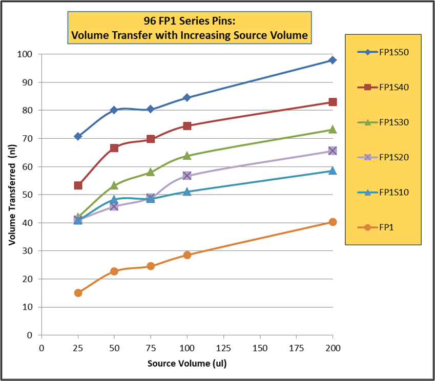
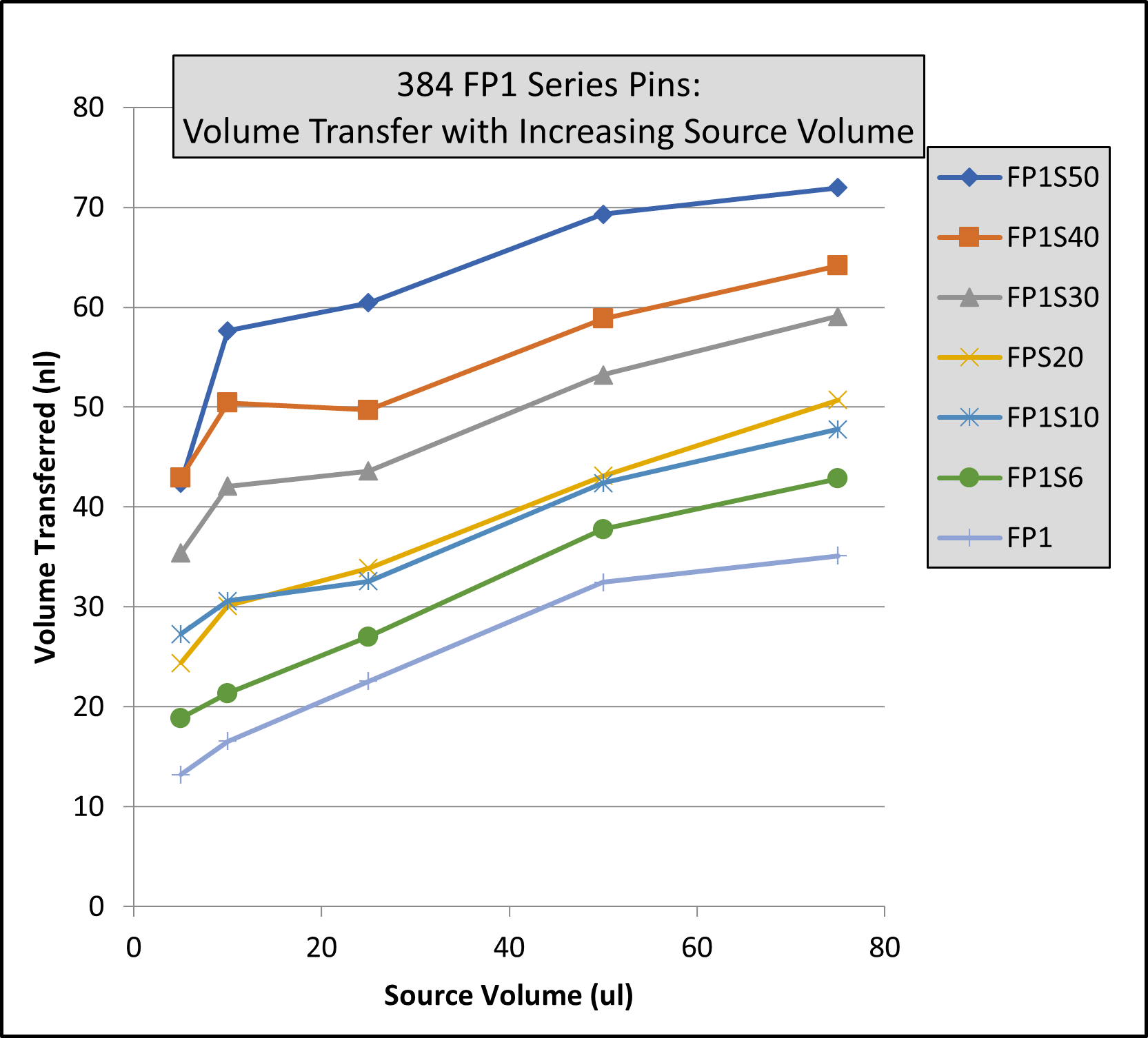
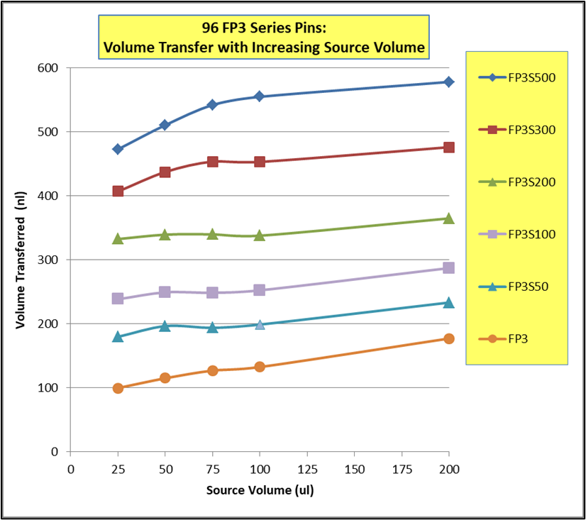
Note: Same volume (200ul for 96 Format and 74 ul for 384 Format) in recipient plates and same pin withdrawal speed for all pins. Changes to pin withdrawal speed or volume in the source plate can result in different volumes being transferred.
Transfer volumes should always be confirmed by customers for their assay conditions and automated system.
Pin Type | Pin Diameter(mm) | Shape | 96 Format Low Range(nL)² | 96 Format High Range(nL)² |
---|---|---|---|---|
FP9 | 0.229 | Solid | 13 | 39 |
FP8 | 0.356 | Solid | 15 | 37 |
FP1 | 0.457 | Solid | 22 | 61 |
FP1S6 | 0.457 | 6nL Slot | 34 | 67 |
FP1S10 | 0.457 | 10nL Slot | 39 | 74 |
FP1S50 | 0.457 | 50nL Slot | 90 | 124 |
FP3 | 0.787 | Solid | 93 | 213 |
FP3S100 | 0.787 | 100nL Slot | 213 | 334 |
FP3S200 | 0.787 | 200nL Slot | 311 | 449 |
FP3S500 | 0.787 | 500nL Slot | 515 | 671 |
FP4 | 0.914 | Solid | 126 | 289 |
Footnotes: (1) Delivery volume range is determined by speed of withdrawal from source liquid: Z-Speed Range = 1.5-30 mm/sec, slow speed = low volume delivery range, fast speed = high volume delivery range (2) 200ul source plate volume per well |
Pin Type | Pin Diameter(mm) | Shape | 96 Format Low Range(nL)² | 96 Format High Range(nL)² |
---|---|---|---|---|
FP9 | 0.229 | Solid | 13 | 38 |
FP8 | 0.356 | Solid | ||
FP1 | 0.457 | Solid | 23 | 60 |
FP1S6 | 0.457 | 6nL Slot | 33 | 67 |
FP1S10 | 0.457 | 10nL Slot | 40 | 75 |
FP1S50 | 0.457 | 50nL Slot | 86 | 119 |
FP3 | 0.787 | Solid | 76 | 209 |
FP3S100 | 0.787 | 100nL Slot | 188 | 324 |
FP3S200 | 0.787 | 200nL Slot | 288 | 436 |
FP3S500 | 0.787 | 500nL Slot | 473 | 649 |
FP4 | 0.914 | Solid | ||
Footnotes: (1) Delivery volume range is determined by speed of withdrawal from source liquid: Z-Speed Range = 1.5-30 mm/sec, slow speed = low volume delivery range, fast speed = high volume delivery range (2) 200ul source plate volume per well |
Pin Type | Pin Diameter(mm) | Shape | Low Range(nL)² | High Range(nL)² |
---|---|---|---|---|
FP | 1.58 | Solid Pointed | 175 | 594 |
FPS.5 | 1.58 | 500nL Slot | 524 | 962 |
FPS | 1.58 | 1000nL Slot | 1056 | 1476 |
FPS2 | 1.58 | 2000nL Slot | 1739 | 2174 |
FPS5 | 1.58 | 5000nL Slot | 5150 | 4953 |
FP6 | 1.58 | Solid Flat | 465 | 960 |
FP6S.5 | 1.58 | 500nL Slot | 934 | 1445 |
FP6S | 1.58 | 1000nL Slot | 1396 | 1930 |
FP6S2 | 1.58 | 2000nL Slot | 2072 | 2637 |
FP6S5 | 1.58 | 5000nL Slot | 4820 | 4693 |
Footnotes:(1) Delivery volume range is determined by speed of withdrawal from source liquid: Z-Speed Range = 1.5-30 mm/sec, slow speed = low volume delivery range, fast speed = high volume delivery range (2) 200ul source plate volume per well for 96 Format and 75ul source plate volume per well for 384 Format |
Pin Type | Pin Diameter(mm) | Shape | 96 Format Low Range(nL)² | 96 Format High Range(nL)² | 384 Format Low Range(nL)³ | 384 Format High Range(nL)³ |
---|---|---|---|---|---|---|
FP9 | 0.229 | Solid | 4 | 10 | 3 | 8 |
FP8 | 0.35 | Solid | 13 | 26 | 6 | 18 |
FP1 | 0.457 | Solid | 18 | 43 | 11 | 31 |
FP1S6 | 0.457 | 6nL Slot | 24 | 49 | 15 | 34 |
FP1S10 | 0.457 | 10nL Slot | 30 | 54 | 21 | 40 |
FP1S20 | 0.457 | 20nL Slot | 37 | 61 | 27 | 46 |
FP1S30 | 0.457 | 30nL Slot | 46 | 68 | 35 | 54 |
FP1S40 | 0.457 | 40nL Slot | 57 | 78 | 45 | 63 |
FP1S50 | 0.457 | 50nL Slot | 70 | 90 | 56 | 75 |
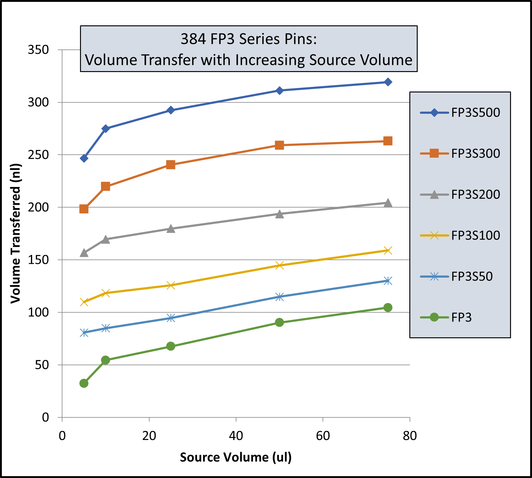
FP3 | 0.787 | Solid | 67 | 139 | 29 | 79 |
FP4 | 0.91 | Solid | 94 | 197 | 34 | 98 |
FP3S100 | 0.787 | 100nL Slot | 175 | 241 | 114 | 163 |
FP3S200 | 0.787 | 200nL Slot | 280 | 332 | 203 | 250 |
FP3S500 | 0.787 | 500nL Slot | 535 | 559 | 427 | 464 |
FP4S1000 | 0.91 | 1000nL Slot | 940 | 1011 | 704 | 800 |
FP4S2000 | 0.91 | 2000nL Slot | 1518 | 1608 | 1277 | 1362 |
Footnotes: (1) Delivery volume range is determined by speed of withdrawal from source liquid: Z-Speed Range = 1.5-30 mm/sec, slow speed = low volume delivery range, fast speed = high volume delivery range (2) 200ul source plate volume per well (3) 75ul source plate volume per well |
Pin Type | Pin Diameter (mm) | Shape | 96 Format Low Range(nL)² | 96 Format High Range(nL)² | 384 Format Low Range(nL)³ | 384 Format High Range(nL)³ |
---|---|---|---|---|---|---|
FP9H | 0.229 | Solid | 4 | 10 | 3 | 8 |
FP8H | 0.35 | Solid | 9 | 24 | 6 | 17 |
FP1H | 0.457 | Solid | 15 | 39 | 9 | 27 |
FP1S6H | 0.457 | 6nL Slot | 23 | 49 | 14 | 32 |
FP1S10H | 0.457 | 10nL Slot | 29 | 53 | 20 | 38 |
FP1S20H | 0.457 | 20nL Slot | 35 | 59 | 26 | 43 |
FP1S30H | 0.457 | 30nL Slot | 47 | 69 | 35 | 53 |
FP1S40H | 0.457 | 40nL Slot | 54 | 75 | 41 | 58 |
FP1S50H | 0.457 | 50nL Slot | 69 | 90 | 57 | 73 |
FP3H | 0.787 | Solid | 67 | 134 | 27 | 76 |
FP4H | 0.91 | Solid | 95 | 189 | 32 | 102 |
FP3S100H | 0.787 | 100nL Slot | 170 | 227 | 108 | 164 |
FP3S200H | 0.787 | 200nL Slot | 266 | 320 | 190 | 239 |
FP3S500H | 0.787 | 500nL Slot | 520 | 542 | 416 | 456 |
FP4S1000H | 0.91 | 1000nL Slot | 932 | 1000 | 741 | 805 |
FP4S2000H | 0.91 | 2000nL Slot | 1571 | 1638 | 1351 | 1423 |
Footnotes: (1) Delivery volume range is determined by speed of withdrawal from source liquid: Z-Speed Range = 1.5-30 mm/sec, slow speed = low volume delivery range, fast speed = high volume delivery range (2) 200ul source plate volume per well (3) 75ul source plate volume per well |
Pin Type | Diameter (mm) | Shape | 96 Format Low Range(nL)² | 96 Format High Range(nL)² | 384 Format Low Range(nL)³ | 384 Format High Range(nL)³ |
---|---|---|---|---|---|---|
FP | 1.58 | Solid Pointed | 147 | 411 | 168 | 395 |
FPS.5 | 1.58 | 500nL Slot | 442 | 704 | 631 | 843 |
FPS | 1.58 | 1000nL Slot | 893 | 1130 | 1343 | 1498 |
FPS2 | 1.58 | 2000nL Slot | 1911 | 2038 | 2607 | 2767 |
FPS5 | 1.58 | 5000nL Slot | 3908 | 4296 | 5180 | 5253 |
FP6 | 1.58 | Solid Flat | 323 | 674 | 154 | 398 |
FP6S.5 | 1.58 | 500nL Slot | 734 | 1042 | 855 | 1053 |
FP6S | 1.58 | 1000nL Slot | 1210 | 1500 | 1638 | 1717 |
FP6S2 | 1.58 | 2000nL Slot | 2299 | 2384 | 2787 | 3068 |
FP6S5 | 1.58 | 5000nL Slot | 4329 | 4656 | 5237 | 5245 |
Footnotes:(1) Delivery volume range is determined by speed of withdrawal from source liquid: Z-Speed Range = 1.5-30 mm/sec, slow speed = low volume delivery range, fast speed = high volume delivery range (2) 200ul source plate volume per well (3) 75ul source plate volume per well |