Powered by Bioz
SpinVessel® ACCESSORY, Straw, 12 Inch, 316L Stainless Steel, 0.62/.63″ OD x (.555″ ID), Seamless, Annealed, Deburred, and Passivated, Used With the 6 Liter SpinVessel®
SpinVessel® ACCESSORY, Straw, 12 Inches Long
SpinVessel® ACCESSORY, Straw, 12 Inch, 316L Stainless Steel, 0.62/.63″ OD x (.555″ ID), Seamless, Annealed, Deburred, and Passivated, Used With the 6 Liter SpinVessel®
| Working Volume | 6L |
|---|---|
| Material | Stainless Steel |
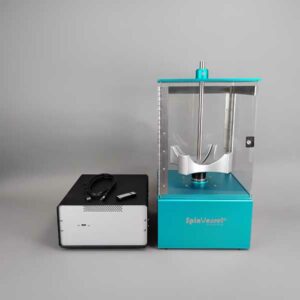
Our unique method of mixing and suspending particulates is predicated on Pulsed Radial Flow. When a circular flowing current of liquid is pushed along by side fins in the bottom of a spinning vessel and then the spin direction is rapidly reversed, when that liquid current strikes the reversing side fin or projection it re-directs the circular liquid flow up the side wall of the vessel as a pulse. For each side fin or projection, there is one pulse. The flow path starts at the bottom of the vessel, then moves up the side wall and when it reaches the top of the vessel it flows down the center of the vessel to the bottom and the circle begins again when the SpinVessel® rotation is reserved again.
Our method of mixing is achieved by integrating radially oriented side fins and projections in a vessel and pairing the vessel to a motorized device that alternatively reverses the vessel’s spin rotation after a defined number of revolutions and various speed settings. The placement of the side fins and projections is designed to avoid contacting pipet tips on robotic liquid handlers.
The optimal SpinVessel® motor settings are dependent upon the circumference of the SpinVessel®, and your application’s specific factors which need to be empirically determined for each application. The smaller the SpinVessel® circumference, the speed in RPM needs to be faster and visa versa. This phenomenon is true because the pulsed Radial Flow strength is generated by the linear speed of the circulating liquid current striking the reversing side fins at the circumference of the SpinVessel®. The faster the fluid current is moving the stronger the pulse. See page 501 of our SLAS Technology paper for a full discussion of this phenomenon.
Other factors to be considered are the density of the particulates, their size, fragility, and shape, as well as the volume and viscosity of the carrier liquid. Start with (100 RPM) and 4 rotations before reversing direction, then work up or down to the appropriate RPMs and number of rotations for your particulate’s density, fragility, and solution viscosity.
It is always a good idea to practice with water in the SpinVessel® to determine a safe RPM, number of rotations, pause and ramp numbers before using expensive reagents.
| Pin | Description | nl Transferred | CV% | |
|---|---|---|---|---|
| 0.229 mm diameter (FP9) | Total Pin | Uncoated | 7.41 | 2.4 |
| Hydrophobic | 7.46 | 5.4 | ||
| 0.229 mm diameter (FP9) | Hanging Drop | Uncoated | N/A | N/A |
| Hydrophobic | 2.09 | 3.8 | ||
| 0.457 mm diameter (FP1) | Total Pin | Uncoated | 33.48 | 3.2 |
| Hydrophobic | 28.17 | 7.5 | ||
| 0.457 mm diameter (FP1) | Hanging Drop | Uncoated | 16.96 | 4.5 |
| Hydrophobic | 8.51 | 0.8 | ||
| 0.787 mm diameter (FP3) | Total Pin | Uncoated | 87.32 | 3.9 |
| Hydrophobic | 77.4 | 3.9 | ||
| 0.787 mm diameter (FP3) | Hanging Drop | Uncoated | 48.77 | 1.2 |
| Hydrophobic | 43.05 | 9.4 | ||
| 1.19 mm diameter (VP 409 & VP 386) | Total Pin | Uncoated | 247.22 | 2.8 |
| Hydrophobic | 192.67 | 2.6 | ||
| 1.19 mm diameter (VP 409 & VP 386) | Hanging Drop | Uncoated | 76.35 | 1.6 |
| Hydrophobic | 108.4 | 2.8 | ||
| 1.58 mm diameter (VP 408 & VP 384) | Total Pin | Uncoated | 273.5 | 4.6 |
| Hydrophobic | 259.25 | 3.1 | ||
| 1.58 mm diameter (VP 408 & VP 384) | Hanging Drop | Uncoated | 201.93 | 5 |
| Hydrophobic | 170.04 | 7.5 |
Transfer Of Horseradish Peroxidase In Tris Buffered Saline With Pin Tools
Coating pins will reduce the total amount of liquid transferred and also reduce the amount of non-specific binding to the stainless-steel pins. If the substance you are transferring has high non-specific binding this will be an important factor in selecting your pins.
| Pin | Description | nl Transferred | CV% | |
|---|---|---|---|---|
| 0.229 mm diameter (FP9) | Total Pin | Uncoated | 7.41 | 2.4 |
| Hydrophobic | 7.46 | 5.4 | ||
| 0.229 mm diameter (FP9) | Hanging Drop | Uncoated | N/A | N/A |
| Hydrophobic | 2.09 | 3.8 | ||
| 0.457 mm diameter (FP1) | Total Pin | Uncoated | 33.48 | 3.2 |
| Hydrophobic | 28.17 | 7.5 | ||
| 0.457 mm diameter (FP1) | Hanging Drop | Uncoated | 16.96 | 4.5 |
| Hydrophobic | 8.51 | 0.8 | ||
| 0.787 mm diameter (FP3) | Total Pin | Uncoated | 87.32 | 3.9 |
| Hydrophobic | 77.4 | 3.9 | ||
| 0.787 mm diameter (FP3) | Hanging Drop | Uncoated | 48.77 | 1.2 |
| Hydrophobic | 43.05 | 9.4 | ||
| 1.19 mm diameter (VP 409 & VP 386) | Total Pin | Uncoated | 247.22 | 2.8 |
| Hydrophobic | 192.67 | 2.6 | ||
| 1.19 mm diameter (VP 409 & VP 386) | Hanging Drop | Uncoated | 76.35 | 1.6 |
| Hydrophobic | 108.4 | 2.8 | ||
| 1.58 mm diameter (VP 408 & VP 384) | Total Pin | Uncoated | 273.5 | 4.6 |
| Hydrophobic | 259.25 | 3.1 | ||
| 1.58 mm diameter (VP 408 & VP 384) | Hanging Drop | Uncoated | 201.93 | 5 |
| Hydrophobic | 170.04 | 7.5 |
Transfer Of Horseradish Peroxidase In Tris Buffered Saline With Pin Tools
Although the slots in the pin are a precise volume, the liquid that is transferred is usually more. The reason for this is due to the surface tension of the liquid causing the liquid in the slot to “bow out” thus increasing the volume of the liquid in the slot. If is important for you to transfer exactly a certain volume we can make custom slots to match the surface tension characteristics of your liquid
| Solvent/Sample | Concentration | CV% | nl FITC Transferred | CV% | nl FITC Transferred |
|---|---|---|---|---|---|
| Uncoated | Uncoated | Hydrophobic Coated | Hydrophobic Coated | ||
| DMSO (-) | 0 | 8.1 | 353.42 | 7.5 | 298.72 |
| DMSO + DNA (mg/ml) | 0.5 | 6.6 | 497.21 | 6.6 | 435.86 |
| 0.25 | 9 | 432.49 | 4.1 | 391.93 | |
| 0.125 | 8.9 | 363.64 | 0.9 | 344.75 | |
| 0.0625 | 2.3 | 381.86 | 2 | 331.68 | |
| 0.0313 | 1.5 | 378.03 | 4.4 | 331.71 | |
| 0.0156 | 1.2 | 357.52 | 1.4 | 329.03 | |
| Tris (-) | 0 | 4.9 | 577.31 | 7.2 | 493.53 |
| Tris + DNA (mg/ml) | 0.5 | 4.5 | 540.53 | 1.1 | 477.5 |
| 0.25 | 4.6 | 518.21 | 6.1 | 456.75 | |
| 0.125 | 15.8 | 583.25 | 4.1 | 438.82 | |
| 0.0625 | 4.2 | 551.17 | 3.1 | 433.69 | |
| 0.0313 | 4.4 | 536.66 | 2.3 | 458.37 | |
| 0.0156 | 2.9 | 528.53 | 1.2 | 441.1 | |
| Tris + BSA (%) | 4 | 5.4 | 462.13 | 11 | 409.27 |
| 1 | 4 | 452.86 | 2.7 | 426.58 | |
| 0.25 | 11.7 | 456.45 | 1.3 | 408.72 | |
| 0.0625 | 1.1 | 445.22 | 6.5 | 393.07 | |
| 0.0156 | 3.7 | 462.85 | 3.9 | 430.2 | |
| 0.0039 | 1.5 | 493.54 | 2.2 | 437.29 | |
| 0.001 | 2.9 | 504.25 | 0.7 | 475.96 |
1. Increasing the concentration of DNA (sheared salmon sperm) to .25 mg/ml significantly increases the volume of DMSO liquid transferred for both coated and uncoated FP3S500 Slot Pins.
2. Increasing the concentration of DNA does not significantly increase the volume of Tris buffer (aqueous) transferred by both coated and uncoated FP3S500 Slot Pins.
3. Increasing the concentration of BSA (Bovine Serum Albumin) significantly decreases the volume of Tris buffer transferred by both coated and uncoated FP3S500 Slot Pins.
4. Hydrophobic coated FP3S500 Slot Pins transferred less DMSO – DNA and less Tris DNA and less Tris BSA than the uncoated FP3S500 Slot Pins.
5. Both coated and uncoated FP3S500 pins transfer significantly more aqueous solution than DMSO.
| Solvent/Sample | Concentration | CV% | nl FITC Transferred | CV% | nl FITC Transferred |
|---|---|---|---|---|---|
| Uncoated | Uncoated | Hydrophobic Coated | Hydrophobic Coated | ||
| DMSO (-) | 0 | 4.2 | 49.38 | 2.1 | 49.31 |
| DMSO + DNA (mg/ml) | 0.5 | 4.9 | 51.24 | 2.6 | 56.79 |
| 0.25 | 1.7 | 50.2 | 1.2 | 49.53 | |
| 0.125 | 1.5 | 51.27 | 2.3 | 49.77 | |
| 0.0625 | 2.2 | 49.34 | 4.1 | 48.19 | |
| 0.0313 | 1.2 | 49.03 | 0.2 | 50.23 | |
| 0.0156 | 2.4 | 45.9 | 1.4 | 46.64 | |
| Tris (-) | 0 | 2.6 | 89.51 | 2.9 | 91.34 |
| Tris + DNA (mg/ml) | 0.5 | 7 | 77.11 | 0.6 | 84.62 |
| 0.25 | 3.9 | 82.22 | 1.6 | 84.89 | |
| 0.125 | 3.9 | 85.42 | 1 | 85.08 | |
| 0.0625 | 1.5 | 85.36 | 2.8 | 85.03 | |
| 0.0313 | 2 | 84.52 | 3 | 88.19 | |
| 0.0156 | 2.6 | 82.92 | 2.8 | 83.2 |
1. In contrast to the FP3S500 data, increasing the concentration of DNA to .25 mg/ml does not significantly increase the volume of DMSO liquid transferred for both coated and uncoated FP1S50 Slot Pins.
2. Increasing the concentration of DNA does not significantly increase the volume of Tris buffer (aqueous) transferred by both coated and uncoated FP1S50 Slot Pins.
3. In contrast to the FP3S500 data, FP1S50 coated pins transferred about the same volume of DNA at all concentrations as did uncoated pins.
4. Both coated and uncoated FP1S50 pins transfer significantly more aqueous solution than DMSO.
5. The differences between the FP3S500 and the FP1S50 pin may be due to the different pin diameter’s effect on contact angle and therefore on the “wetting” of the pin. See the diagram on the link to / ah energy system.
| Pin | Description | nl Transferred | CV% | |
|---|---|---|---|---|
| 0.229 mm diameter (FP9) | Total Pin | Uncoated | 7.41 | 2.4 |
| Hydrophobic | 7.46 | 5.4 | ||
| 0.229 mm diameter (FP9) | Hanging Drop | Uncoated | N/A | N/A |
| Hydrophobic | 2.09 | 3.8 | ||
| 0.457 mm diameter (FP1) | Total Pin | Uncoated | 33.48 | 3.2 |
| Hydrophobic | 28.17 | 7.5 | ||
| 0.457 mm diameter (FP1) | Hanging Drop | Uncoated | 16.96 | 4.5 |
| Hydrophobic | 8.51 | 0.8 | ||
| 0.787 mm diameter (FP3) | Total Pin | Uncoated | 87.32 | 3.9 |
| Hydrophobic | 77.4 | 3.9 | ||
| 0.787 mm diameter (FP3) | Hanging Drop | Uncoated | 48.77 | 1.2 |
| Hydrophobic | 43.05 | 9.4 | ||
| 1.19 mm diameter (VP 409 & VP 386) | Total Pin | Uncoated | 247.22 | 2.8 |
| Hydrophobic | 192.67 | 2.6 | ||
| 1.19 mm diameter (VP 409 & VP 386) | Hanging Drop | Uncoated | 76.35 | 1.6 |
| Hydrophobic | 108.4 | 2.8 | ||
| 1.58 mm diameter (VP 408 & VP 384) | Total Pin | Uncoated | 273.5 | 4.6 |
| Hydrophobic | 259.25 | 3.1 | ||
| 1.58 mm diameter (VP 408 & VP 384) | Hanging Drop | Uncoated | 201.93 | 5 |
| Hydrophobic | 170.04 | 7.5 |
Hydrophobic coating pins will reduce the total amount of aqueous HRP liquid transferred and also reduce the amount of non-specific binding to the stainless-steel pins. If the substance you are transferring has high non-specific binding this will be an important factor in selecting your pins.
Pin diameter also has an effect on the degree of reduction of liquid transfer with hydrophobic coating as the smaller the diameter the less the reduction of transfer. This is most likely due to the curvature of the pin affecting the wetting contact angle
| Pin | Description | nl Transferred | CV% | ||
|---|---|---|---|---|---|
| 0.457 mm diameter (FP1) | 6 nl Slot | Total Pin* | Uncoated | 25.6 | 10.8 |
| Hydrophobic | N/A | N/A | |||
| 10 nl Slot | Total Pin* | Uncoated | 23.36 | 6.1 | |
| Hydrophobic | 25.85 | 6.9 | |||
| 50 nl Slot | Total Pin* | Uncoated | 67.83 | 2.5 | |
| Hydrophobic | N/A | N/A | |||
| 0.787 mm diameter (FP3) | 100 nl Slot | Total Pin* | Uncoated | 180.32 | 7.2 |
| Hydrophobic | 205.84 | 5.5 | |||
| 200 nl Slot | Total Pin* | Uncoated | 277.82 | 4.9 | |
| Hydrophobic | 287.3 | 3.8 | |||
| 500 nl Slot | Total Pin* | Uncoated | 581.16 | 5.2 | |
| Hydrophobic | 555.69 | 3 |
Hydrophobic coating pins will slightly increase the total amount of DMSO FITC liquid transferred.
| Pin | Description | nl Transferred | CV% | |
|---|---|---|---|---|
| 0.787 mm diameter (FP3) | 100 nl Slot Total Pin, Including Slot | Uncoated | 195.69 | 1.6 |
| Hydrophobic | 170.2 | 2.9 | ||
| 0.787 mm diameter (FP3) | 100 nl Slot, Slot Only | Uncoated | 149.67 | 4.9 |
| Hydrophobic | 129.61 | 7.6 | ||
| 0.787 mm diameter (FP3) | 200 nl Slot Total Pin, Including Slot | Uncoated | 269.77 | 1.9 |
| Hydrophobic | 228.62 | 17.1 | ||
| 0.787 mm diameter (FP3) | 200 nl Slot, Slot Only | Uncoated | 237.52 | 8.9 |
| Hydrophobic | 186.9 | 5.9 |
Although the slots in the pin are a precise volume, the liquid that is transferred is usually more because of the volume carried on the sides of the pins.
As seen with other aqueous data the amount transferred on hydrophobic coated Slot pins is less than on uncoated Solid or Slot pins. Thus Hydrophobic coating has the most effect on aqueous transfers.

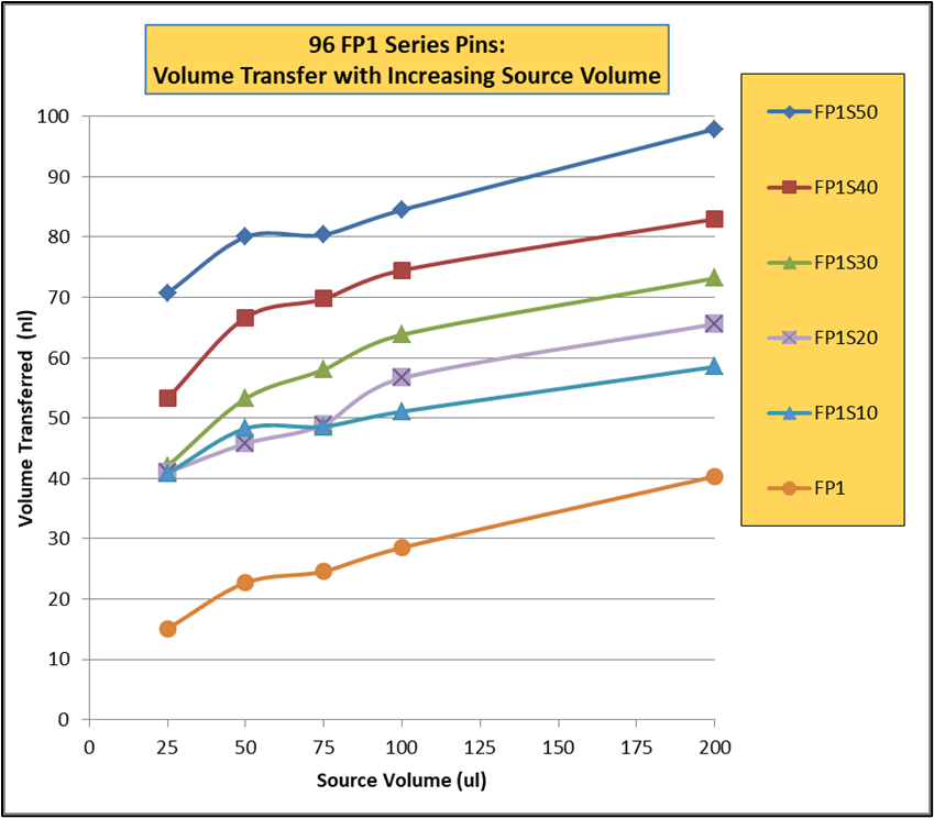
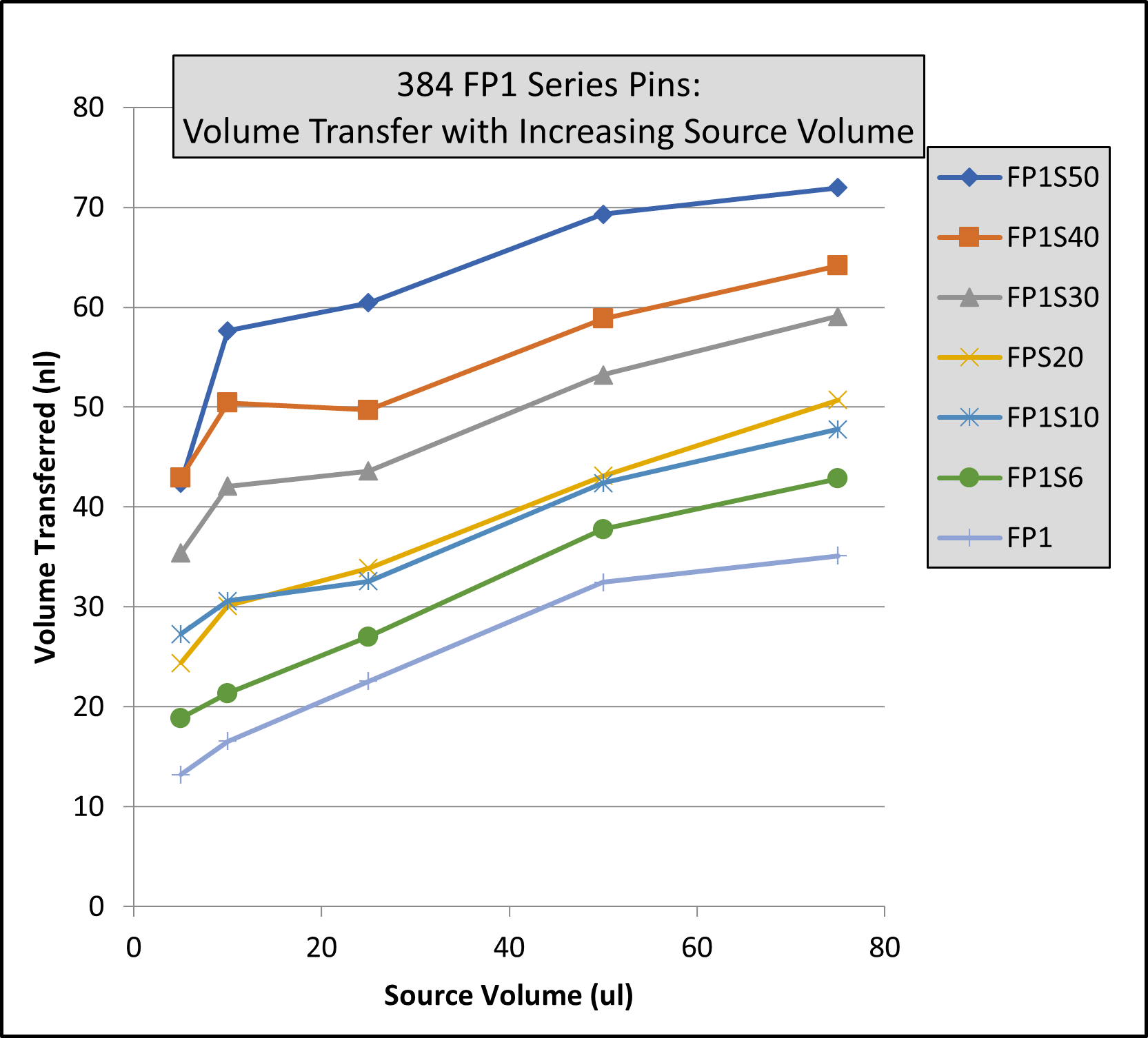
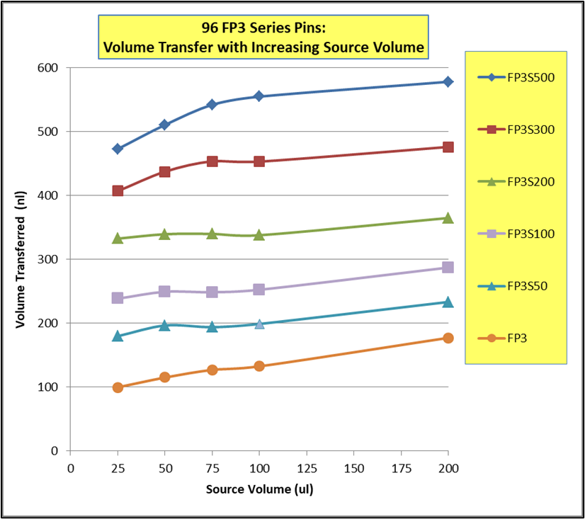
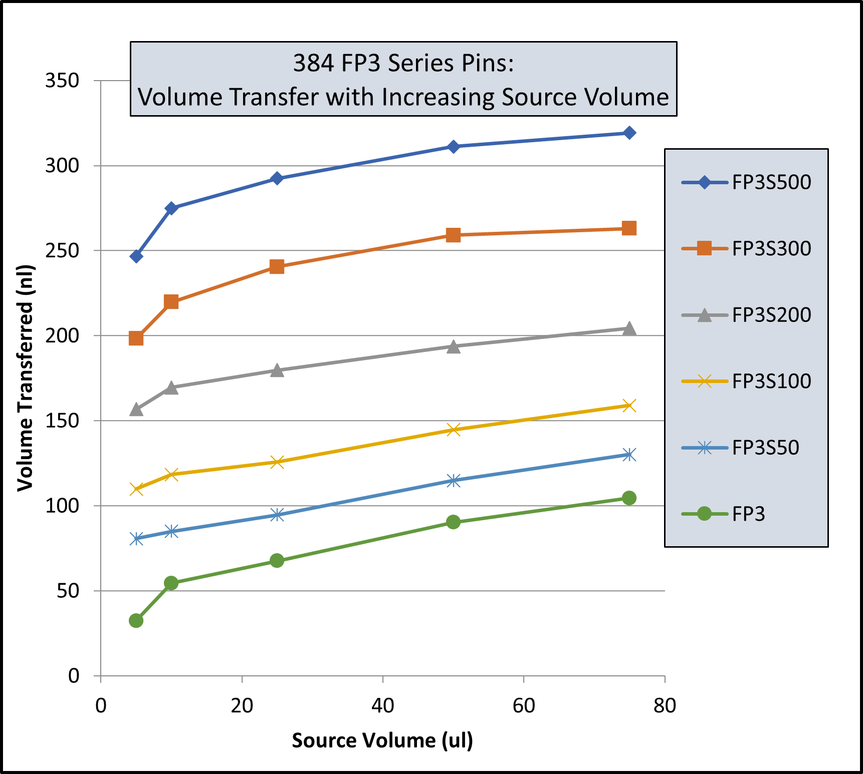
Note: Same volume (200ul for 96 Format and 74 ul for 384 Format) in recipient plates and same pin withdrawal speed for all pins. Changes to pin withdrawal speed or volume in the source plate can result in different volumes being transferred.
Transfer volumes should always be confirmed by customers for their assay conditions and automated system.
| Pin Type | Pin Diameter(mm) | Shape | 96 Format Low Range(nL)² | 96 Format High Range(nL)² |
|---|---|---|---|---|
| FP9 | 0.229 | Solid | 13 | 39 |
| FP8 | 0.356 | Solid | 15 | 37 |
| FP1 | 0.457 | Solid | 22 | 61 |
| FP1S6 | 0.457 | 6nL Slot | 34 | 67 |
| FP1S10 | 0.457 | 10nL Slot | 39 | 74 |
| FP1S50 | 0.457 | 50nL Slot | 90 | 124 |
| FP3 | 0.787 | Solid | 93 | 213 |
| FP3S100 | 0.787 | 100nL Slot | 213 | 334 |
| FP3S200 | 0.787 | 200nL Slot | 311 | 449 |
| FP3S500 | 0.787 | 500nL Slot | 515 | 671 |
| FP4 | 0.914 | Solid | 126 | 289 |
| Footnotes: (1) Delivery volume range is determined by speed of withdrawal from source liquid: Z-Speed Range = 1.5-30 mm/sec, slow speed = low volume delivery range, fast speed = high volume delivery range (2) 200ul source plate volume per well | ||||
| Pin Type | Pin Diameter(mm) | Shape | 96 Format Low Range(nL)² | 96 Format High Range(nL)² |
|---|---|---|---|---|
| FP9 | 0.229 | Solid | 13 | 38 |
| FP8 | 0.356 | Solid | ||
| FP1 | 0.457 | Solid | 23 | 60 |
| FP1S6 | 0.457 | 6nL Slot | 33 | 67 |
| FP1S10 | 0.457 | 10nL Slot | 40 | 75 |
| FP1S50 | 0.457 | 50nL Slot | 86 | 119 |
| FP3 | 0.787 | Solid | 76 | 209 |
| FP3S100 | 0.787 | 100nL Slot | 188 | 324 |
| FP3S200 | 0.787 | 200nL Slot | 288 | 436 |
| FP3S500 | 0.787 | 500nL Slot | 473 | 649 |
| FP4 | 0.914 | Solid | ||
| Footnotes: (1) Delivery volume range is determined by speed of withdrawal from source liquid: Z-Speed Range = 1.5-30 mm/sec, slow speed = low volume delivery range, fast speed = high volume delivery range (2) 200ul source plate volume per well | ||||
| Pin Type | Pin Diameter(mm) | Shape | Low Range(nL)² | High Range(nL)² |
|---|---|---|---|---|
| FP | 1.58 | Solid Pointed | 175 | 594 |
| FPS.5 | 1.58 | 500nL Slot | 524 | 962 |
| FPS | 1.58 | 1000nL Slot | 1056 | 1476 |
| FPS2 | 1.58 | 2000nL Slot | 1739 | 2174 |
| FPS5 | 1.58 | 5000nL Slot | 5150 | 4953 |
| FP6 | 1.58 | Solid Flat | 465 | 960 |
| FP6S.5 | 1.58 | 500nL Slot | 934 | 1445 |
| FP6S | 1.58 | 1000nL Slot | 1396 | 1930 |
| FP6S2 | 1.58 | 2000nL Slot | 2072 | 2637 |
| FP6S5 | 1.58 | 5000nL Slot | 4820 | 4693 |
| Footnotes:(1) Delivery volume range is determined by speed of withdrawal from source liquid: Z-Speed Range = 1.5-30 mm/sec, slow speed = low volume delivery range, fast speed = high volume delivery range (2) 200ul source plate volume per well for 96 Format and 75ul source plate volume per well for 384 Format |
||||
| Pin Type | Pin Diameter(mm) | Shape | 96 Format Low Range(nL)² | 96 Format High Range(nL)² | 384 Format Low Range(nL)³ | 384 Format High Range(nL)³ |
|---|---|---|---|---|---|---|
| FP9 | 0.229 | Solid | 4 | 10 | 3 | 8 |
| FP8 | 0.35 | Solid | 13 | 26 | 6 | 18 |
| FP1 | 0.457 | Solid | 18 | 43 | 11 | 31 |
| FP1S6 | 0.457 | 6nL Slot | 24 | 49 | 15 | 34 |
| FP1S10 | 0.457 | 10nL Slot | 30 | 54 | 21 | 40 |
| FP1S20 | 0.457 | 20nL Slot | 37 | 61 | 27 | 46 |
| FP1S30 | 0.457 | 30nL Slot | 46 | 68 | 35 | 54 |
| FP1S40 | 0.457 | 40nL Slot | 57 | 78 | 45 | 63 |
| FP1S50 | 0.457 | 50nL Slot | 70 | 90 | 56 | 75 |
| FP3 | 0.787 | Solid | 67 | 139 | 29 | 79 |
| FP4 | 0.91 | Solid | 94 | 197 | 34 | 98 |
| FP3S100 | 0.787 | 100nL Slot | 175 | 241 | 114 | 163 |
| FP3S200 | 0.787 | 200nL Slot | 280 | 332 | 203 | 250 |
| FP3S500 | 0.787 | 500nL Slot | 535 | 559 | 427 | 464 |
| FP4S1000 | 0.91 | 1000nL Slot | 940 | 1011 | 704 | 800 |
| FP4S2000 | 0.91 | 2000nL Slot | 1518 | 1608 | 1277 | 1362 |
| Footnotes: (1) Delivery volume range is determined by speed of withdrawal from source liquid: Z-Speed Range = 1.5-30 mm/sec, slow speed = low volume delivery range, fast speed = high volume delivery range (2) 200ul source plate volume per well (3) 75ul source plate volume per well | ||||||
| Pin Type | Pin Diameter (mm) | Shape | 96 Format Low Range(nL)² | 96 Format High Range(nL)² | 384 Format Low Range(nL)³ | 384 Format High Range(nL)³ |
|---|---|---|---|---|---|---|
| FP9H | 0.229 | Solid | 4 | 10 | 3 | 8 |
| FP8H | 0.35 | Solid | 9 | 24 | 6 | 17 |
| FP1H | 0.457 | Solid | 15 | 39 | 9 | 27 |
| FP1S6H | 0.457 | 6nL Slot | 23 | 49 | 14 | 32 |
| FP1S10H | 0.457 | 10nL Slot | 29 | 53 | 20 | 38 |
| FP1S20H | 0.457 | 20nL Slot | 35 | 59 | 26 | 43 |
| FP1S30H | 0.457 | 30nL Slot | 47 | 69 | 35 | 53 |
| FP1S40H | 0.457 | 40nL Slot | 54 | 75 | 41 | 58 |
| FP1S50H | 0.457 | 50nL Slot | 69 | 90 | 57 | 73 |
| FP3H | 0.787 | Solid | 67 | 134 | 27 | 76 |
| FP4H | 0.91 | Solid | 95 | 189 | 32 | 102 |
| FP3S100H | 0.787 | 100nL Slot | 170 | 227 | 108 | 164 |
| FP3S200H | 0.787 | 200nL Slot | 266 | 320 | 190 | 239 |
| FP3S500H | 0.787 | 500nL Slot | 520 | 542 | 416 | 456 |
| FP4S1000H | 0.91 | 1000nL Slot | 932 | 1000 | 741 | 805 |
| FP4S2000H | 0.91 | 2000nL Slot | 1571 | 1638 | 1351 | 1423 |
| Footnotes: (1) Delivery volume range is determined by speed of withdrawal from source liquid: Z-Speed Range = 1.5-30 mm/sec, slow speed = low volume delivery range, fast speed = high volume delivery range (2) 200ul source plate volume per well (3) 75ul source plate volume per well | ||||||
| Pin Type | Diameter (mm) | Shape | 96 Format Low Range(nL)² | 96 Format High Range(nL)² | 384 Format Low Range(nL)³ | 384 Format High Range(nL)³ |
|---|---|---|---|---|---|---|
| FP | 1.58 | Solid Pointed | 147 | 411 | 168 | 395 |
| FPS.5 | 1.58 | 500nL Slot | 442 | 704 | 631 | 843 |
| FPS | 1.58 | 1000nL Slot | 893 | 1130 | 1343 | 1498 |
| FPS2 | 1.58 | 2000nL Slot | 1911 | 2038 | 2607 | 2767 |
| FPS5 | 1.58 | 5000nL Slot | 3908 | 4296 | 5180 | 5253 |
| FP6 | 1.58 | Solid Flat | 323 | 674 | 154 | 398 |
| FP6S.5 | 1.58 | 500nL Slot | 734 | 1042 | 855 | 1053 |
| FP6S | 1.58 | 1000nL Slot | 1210 | 1500 | 1638 | 1717 |
| FP6S2 | 1.58 | 2000nL Slot | 2299 | 2384 | 2787 | 3068 |
| FP6S5 | 1.58 | 5000nL Slot | 4329 | 4656 | 5237 | 5245 |
| Footnotes:(1) Delivery volume range is determined by speed of withdrawal from source liquid: Z-Speed Range = 1.5-30 mm/sec, slow speed = low volume delivery range, fast speed = high volume delivery range (2) 200ul source plate volume per well (3) 75ul source plate volume per well |
||||||