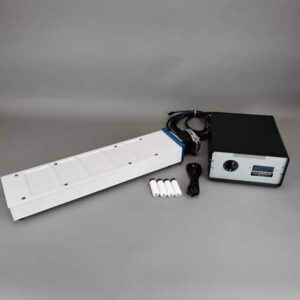
Alligator Vertical Tumble Stirrers
The Alligator Magnetic Vertical Tumble Stirrer uses patented stir-cylinder technology to mix large numbers of samples in tubes, vials, bottles, and microplates (USA Patent #6,176,609). Instead of spinning a magnetic stir bar about the horizontal plane like the standard magnetic flask stirrer, the Alligator Vertical Tumble Stirrer causes stir elements of all sizes and shapes to tumble vertically end-over-end inside each well or vessel. The Alligator Vertical Tumble Stirrer will stir all types of microplates of any volume or format. It will also stir V and U bottom microplates, PCR plates, micro-centrifuge tubes, test tubes, syringes, vials and bottles, and specially designed troughs and reservoirs.
Advantages of the Vertical Tumble Stirring System
- Can stir in any vessel regardless of the size or shape
- High–Throughput Stirring in stacks of Microplates
- Can increase the aeration of microbial cultures and increase yield
- Complete stirring of large numbers of samples
- Can stir chemical reactions to speed completion
- Can stir and heat to 200°C at the same time
- Can run multiple experiments in parallel
- Get more reactions per gram of starting material
- Will stir even 100,000 centistoke viscous solutions (6.6 times more viscous than honey)
- Will stir even thick slurries and emulsions
- No cross contamination – wells do not have to be sealed
- Simple to operate, full-speed control
- Can set exact RPM for reproducible results day to day
- Designed to be compatible with most robotic systems
- Flexibility of stir deck alignment
- Custom designs are not a problem
- Durable – Can stir continuously for years without maintenance
- Computer control available
- Available in 110 volt and 220 volt (CE compliant) versions
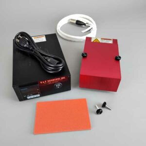
Many Models Available
Using the most powerful permanent magnets manufactured, we make many different models of Vertical Tumble Stirrers that fit the many varied applications and requirements of our customers. Requirements for heating and continuous stirring for a long period of time demand special Vertical Tumble Stirrers that are resistant to heat and with motors capable of working under high loads for extended periods. We make our Vertical Tumble Stirrers heat resistant using Mica. The Mica deck will accommodate three of our V&P heat blocks operating at 200°C. Please check with our knowledgeable staff to help you make the appropriate selection for your application. Our specialty is flexibility- let us know if you have a custom application today!
Published Articles
See published articles that cite using our Stirrer products.
Stir Elements Designed for Vertical Tumble Stirring
We offer a large assortment of economical magnetic Stainless Steel Stir Elements from Stir StiXs to Discs to bars and dowels to fit into any well, vial, tube, or syringe. Check out the Stir Element page for more information on coatings and dimensions.
We also sell Alnico and Rare Earth Magnetic Stir Bars for more viscous solutions.
Tumble Stirring Viscous Solutions
The ability to stir extremely viscous solutions, slurries, and emulsions is a very useful characteristic of the V&P Alligator Tumble Stirrers. Our Vertical Tumble Stirrers and Stir Elements have the ability to mix even solutions of 100,000 centistokes (6.6 times more viscous than honey).
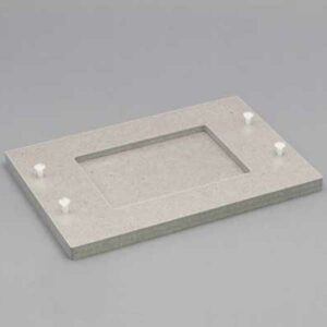
Flick ‘N Blot Magnetic Separation Plates Overview
Fast, Reliable, Pipette-Free Magnetic Bead Separation Alternative
What’s Flick ‘N Blot?
Engineered to remove supernatant and wash buffers efficiently. We’ve taken the versatility of our magnetic separation plates and developed a new system for scientists to simply ‘flick’ off the supernatants and wash buffers without disturbing your magnetic bead pellets and fear of losing samples.
By securing the microplate directly onto a magnetic separation plate, the entire assembly can be inverted and flicked, allowing the decanting of non-viscous supernatants while maintaining pellet integrity. This approach adapts the familiar ELISA plate wash decanting technique that’s now adapted for magnetic bead assays, eliminating the need for automated liquid handling systems or manual pipetting – ideal for budget-friendly high-throughput applications. Just flick ‘n blot!
System Compatibility:
Supported Plate Formats
- 96-well plates (standard and deep-well): round bottom, v-bottom, flat-bottom, conical
- 384-well plate (standard): flat-bottom
Pelleting Configurations
- Single-sided bottom pelleting
- Four-sided bottom pelleting
- Corner-offset (center corner) pelleting
- Centralized bottom pelleting
Whether you’re running nucleic acid purifications, protein isolations, or immunoassays, Flick ‘N Blot simplifies your workflow and reduces consumable waste.
Optimizing Your Assay?
Selecting the optimal magnetic separation plate depends on several critical factors, including bead size, concentration, magnetic field geometry, and assay volume. We know how important precision and reproducibility are to your experiments.
To help make the decision easier, we’ve put together a detailed guide to help you navigate your options. Explore our blog: “Choose Your Microplates Wisely!” to select the right solution for your lab today.
Magnetic Field Strength versus Distance from the Alligator Magnetic Tumble Stirrer Deck
Makers of cardiac pacemakers have placed magnetic switches in them that can be activated when the pacemaker is in a 5-gauss magnetic field. The critical 5 gauss line varies from 5.5″ to 22.8″ above the deck or cylinder guard with our Alligator Tumble Stirrers. The graph indicates that the magnetic field falls off very fast with distance. The distance above the deck to achieve a 5-gauss reading is 10″ for the VP 710C5-7A and 16″ for the VP 710E5X.
However, as a safety factor, we recommend that people with pacemakers keep at least 36″ or 91 cm from the Alligator Vertical Tumble Stirrers and the Vortex Lateral Tumble Stirrer. V&P does not make any claims in regard to the validity of the 5 gauss threshold for deactivating implanted medical devices. The 5 gauss magnetic field is a guideline to avoid risks associated with magnets and implanted medical devices such as pacemakers. For more information, please consult your physician. We try to position the magnet as close to the deck as possible given the constraints of the magnetic cylinders and deck design. Note the distance between the magnet surface and the surface of the deck varies for each magnetic tumble stirrer design and thus the gauss levels at the surface of the deck vary.

")


 Powered by Bioz