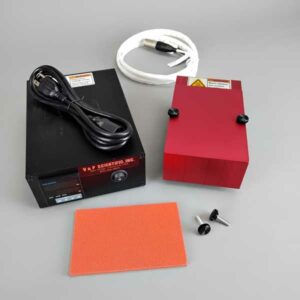
HEATER/CHILLER, 2 Deep Chambers, Recirculating Fluid Block, for Deep or Standard Well Format, Special Design to Minimize Eddy Currents When Used on a Tumble Stirrer, Mica Insulation on Bottom to Fit VP 710L5-1 Deck, 120 Volts, Includes Low-temperature Fittings, Designed to Operate at -70°C
Chamber Depth
Either
No of Chambers
1
Application
Heat or Chill and Stir
Temp Range
-70 to 100 C
Power Supply Input
220 Volts
SLAS Base
Yes
Heat Block Overview
V&P Scientific builds robust, low-profile, ambient to 200oC Heat Blocks that enable heating and stirring in standard microplates, deep well microplates, or reaction blocks of glass tubes and sealed vials. They are constructed out of a specially designed Eddy Current defeating aluminum designed to be used with our strong NdFeB Tumble Stirrers. Although aluminum is not magnetic, when magnetic lines of flux pass through it, an eddy current of electricity is generated that heats the aluminum and causes the motor that is generating the magnetic field movement to work much harder. That is why we invented the Eddy Current defeating design. The low profile design also minimizes the distance from the samples to the magnetic field thus maximizing the stirring power of even viscous materials.
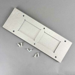
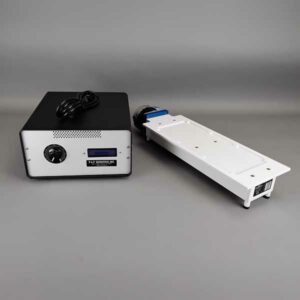
Each Heat Block comes with one or more SLAS Adaptor Bases made of Mica that are attached to the Heat Block’s underside. This base provides heat protection for surfaces below the Heat Block and facilitates its use in microplate-configured locations. The Mica is safety rated by UL laboratories as UL 94VO. Another advantage of our design is that we have separated the control panel from the actual heating block. Thus, the Heat Block’s placement on the deck of a robotic workstation is seamless.
Our temperature controllers all use an RTD (Resistive Thermal Device) heat sensor. RTD sensors are advantageous because they work in moving magnetic fields generated by V&P Tumble Stirrers while Thermocouples do not work in magnetic fields. This is important when heating and stirring simultaneously.
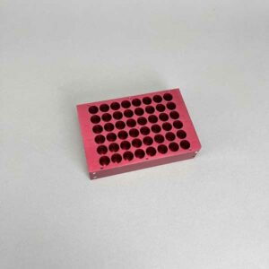
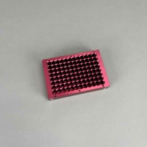
The VP 741 Series and VP 742 Series Heat Blocks have deep chambers and a lid that can be screwed into place to hold Cap Mats or other sealing materials in place while high temperatures are reached. Heating and simultaneously stirring are very useful in redox chemical reactions. Our deep chamber Heat Blocks all come with a U-shaped insert that allows easy removal of standard microplates or other short labware.
The VP 744 Series Heat Blocks are heated or cooled by recirculating hot or cold fluid in the heat exchange channels in the blocks.
The following graph contains data generated in a VP 741ABZ-R-MB Heat Block using a deep well 96 microplate with 2 ml of water in each well. The RTD of the controller is embedded in the aluminum at the base of the Heat Block. The Control temperature was set to 80° C and temperature readings were taken in microplate wells located at the middle (C6), side (A6), and corner (A12) positions and plotted against time. As can be seen in the graph the temperature in the wells plateau at 4 to 6° below the set temperature of 80° C. This difference between the set temperature and the well temperature needs to be determined and compensated for, in your system using your fluid, your volume, and your microplate or other vessels. This difference in set temperature and well temperature is due to the loss of heat transfer between the aluminum and the microplate and the fluid in the well. Also note the best heat transfer occurs in the wells with the greatest contact with the aluminum of the Heat Block, and with time these approach the same temperature. This is why we make Heat Block accessories that maximized the contact between the Heat Block and the microplate or vessel.
Applications
The applications for Heat Blocks in Chemistry and Biology especially when combined with mixing are almost too many to enumerate.
Our Tumble Stirrers and Heat Blocks are used in conjunction for a variety of applications such as accelerating chemical, enzymatic and biological reactions in:
Redox parallel synthesis to develop new drugs Endorsement
Photoredox synthesis to develop new drugs
Heating to different temperatures coupled with mixing to determine the solubility of a compound
Heating to different temperatures and mixing to determine the optimum temperature for the enzymatic hydrolysis of steryl glucosides
Heating and stirring chemical reactions to speed completion
Miniaturization of fermentations and chemical reactions
Drug Susceptibility Assays
Resoluabilize dried extracts from large screening libraries
Protein Expression Screen
Thorough mixing of heated slurries, viscous solutions, and emulsions
Thorough mixing of heated immiscible liquids
Resuspend chemical libraries after storage by heating and mixing
Solid Pin Delivery Data For Aqueous Solutions In 96 Format With Uncoated And /Ah Hydrophobic Coated Pins
Pin
Description
nl Transferred
CV%
0.229 mm diameter (FP9)
Total Pin
Uncoated
7.41
2.4
Hydrophobic
7.46
5.4
0.229 mm diameter (FP9)
Hanging Drop
Uncoated
N/A
N/A
Hydrophobic
2.09
3.8
0.457 mm diameter (FP1)
Total Pin
Uncoated
33.48
3.2
Hydrophobic
28.17
7.5
0.457 mm diameter (FP1)
Hanging Drop
Uncoated
16.96
4.5
Hydrophobic
8.51
0.8
0.787 mm diameter (FP3)
Total Pin
Uncoated
87.32
3.9
Hydrophobic
77.4
3.9
0.787 mm diameter (FP3)
Hanging Drop
Uncoated
48.77
1.2
Hydrophobic
43.05
9.4
1.19 mm diameter (VP 409 & VP 386)
Total Pin
Uncoated
247.22
2.8
Hydrophobic
192.67
2.6
1.19 mm diameter (VP 409 & VP 386)
Hanging Drop
Uncoated
76.35
1.6
Hydrophobic
108.4
2.8
1.58 mm diameter (VP 408 & VP 384)
Total Pin
Uncoated
273.5
4.6
Hydrophobic
259.25
3.1
1.58 mm diameter (VP 408 & VP 384)
Hanging Drop
Uncoated
201.93
5
Hydrophobic
170.04
7.5
Transfer Of Horseradish Peroxidase In Tris Buffered Saline With Pin Tools
Conclusion
Coating pins will reduce the total amount of liquid transferred and also reduce the amount of non-specific binding to the stainless-steel pins. If the substance you are transferring has high non-specific binding this will be an important factor in selecting your pins.
Slot Pin Delivery Data For Aqueous Solutions In 96 Format With Uncoated And /Ah Hydrophobic Coated Pin
Pin
Description
nl Transferred
CV%
0.229 mm diameter (FP9)
Total Pin
Uncoated
7.41
2.4
Hydrophobic
7.46
5.4
0.229 mm diameter (FP9)
Hanging Drop
Uncoated
N/A
N/A
Hydrophobic
2.09
3.8
0.457 mm diameter (FP1)
Total Pin
Uncoated
33.48
3.2
Hydrophobic
28.17
7.5
0.457 mm diameter (FP1)
Hanging Drop
Uncoated
16.96
4.5
Hydrophobic
8.51
0.8
0.787 mm diameter (FP3)
Total Pin
Uncoated
87.32
3.9
Hydrophobic
77.4
3.9
0.787 mm diameter (FP3)
Hanging Drop
Uncoated
48.77
1.2
Hydrophobic
43.05
9.4
1.19 mm diameter (VP 409 & VP 386)
Total Pin
Uncoated
247.22
2.8
Hydrophobic
192.67
2.6
1.19 mm diameter (VP 409 & VP 386)
Hanging Drop
Uncoated
76.35
1.6
Hydrophobic
108.4
2.8
1.58 mm diameter (VP 408 & VP 384)
Total Pin
Uncoated
273.5
4.6
Hydrophobic
259.25
3.1
1.58 mm diameter (VP 408 & VP 384)
Hanging Drop
Uncoated
201.93
5
Hydrophobic
170.04
7.5
Transfer Of Horseradish Peroxidase In Tris Buffered Saline With Pin Tools
Conclusion
Although the slots in the pin are a precise volume, the liquid that is transferred is usually more. The reason for this is due to the surface tension of the liquid causing the liquid in the slot to “bow out” thus increasing the volume of the liquid in the slot. If is important for you to transfer exactly a certain volume we can make custom slots to match the surface tension characteristics of your liquid
Liquid Surface Tension
Effect Of DNA Or BSA Concentration On Slot Pin Transfers Of Uncoated And Hydrophobic Coated Pins (FP3CS500)
Solvent/Sample
Concentration
CV%
nl FITC Transferred
CV%
nl FITC Transferred
Uncoated
Uncoated
Hydrophobic Coated
Hydrophobic Coated
DMSO (-)
0
8.1
353.42
7.5
298.72
DMSO + DNA (mg/ml)
0.5
6.6
497.21
6.6
435.86
0.25
9
432.49
4.1
391.93
0.125
8.9
363.64
0.9
344.75
0.0625
2.3
381.86
2
331.68
0.0313
1.5
378.03
4.4
331.71
0.0156
1.2
357.52
1.4
329.03
Tris (-)
0
4.9
577.31
7.2
493.53
Tris + DNA (mg/ml)
0.5
4.5
540.53
1.1
477.5
0.25
4.6
518.21
6.1
456.75
0.125
15.8
583.25
4.1
438.82
0.0625
4.2
551.17
3.1
433.69
0.0313
4.4
536.66
2.3
458.37
0.0156
2.9
528.53
1.2
441.1
Tris + BSA (%)
4
5.4
462.13
11
409.27
1
4
452.86
2.7
426.58
0.25
11.7
456.45
1.3
408.72
0.0625
1.1
445.22
6.5
393.07
0.0156
3.7
462.85
3.9
430.2
0.0039
1.5
493.54
2.2
437.29
0.001
2.9
504.25
0.7
475.96
Conclusions
1. Increasing the concentration of DNA (sheared salmon sperm) to .25 mg/ml significantly increases the volume of DMSO liquid transferred for both coated and uncoated FP3S500 Slot Pins. 2. Increasing the concentration of DNA does not significantly increase the volume of Tris buffer (aqueous) transferred by both coated and uncoated FP3S500 Slot Pins. 3. Increasing the concentration of BSA (Bovine Serum Albumin) significantly decreases the volume of Tris buffer transferred by both coated and uncoated FP3S500 Slot Pins. 4. Hydrophobic coated FP3S500 Slot Pins transferred less DMSO – DNA and less Tris DNA and less Tris BSA than the uncoated FP3S500 Slot Pins. 5. Both coated and uncoated FP3S500 pins transfer significantly more aqueous solution than DMSO.
Effect Of DNA Or BSA Concentration On Slot Pin Transfers Of Uncoated And Hydrophobic Coated Pins (FP1CS50)
Solvent/Sample
Concentration
CV%
nl FITC Transferred
CV%
nl FITC Transferred
Uncoated
Uncoated
Hydrophobic Coated
Hydrophobic Coated
DMSO (-)
0
4.2
49.38
2.1
49.31
DMSO + DNA (mg/ml)
0.5
4.9
51.24
2.6
56.79
0.25
1.7
50.2
1.2
49.53
0.125
1.5
51.27
2.3
49.77
0.0625
2.2
49.34
4.1
48.19
0.0313
1.2
49.03
0.2
50.23
0.0156
2.4
45.9
1.4
46.64
Tris (-)
0
2.6
89.51
2.9
91.34
Tris + DNA (mg/ml)
0.5
7
77.11
0.6
84.62
0.25
3.9
82.22
1.6
84.89
0.125
3.9
85.42
1
85.08
0.0625
1.5
85.36
2.8
85.03
0.0313
2
84.52
3
88.19
0.0156
2.6
82.92
2.8
83.2
Conclusions
1. In contrast to the FP3S500 data, increasing the concentration of DNA to .25 mg/ml does not significantly increase the volume of DMSO liquid transferred for both coated and uncoated FP1S50 Slot Pins. 2. Increasing the concentration of DNA does not significantly increase the volume of Tris buffer (aqueous) transferred by both coated and uncoated FP1S50 Slot Pins. 3. In contrast to the FP3S500 data, FP1S50 coated pins transferred about the same volume of DNA at all concentrations as did uncoated pins. 4. Both coated and uncoated FP1S50 pins transfer significantly more aqueous solution than DMSO. 5. The differences between the FP3S500 and the FP1S50 pin may be due to the different pin diameter’s effect on contact angle and therefore on the “wetting” of the pin. See the diagram on the link to / ah energy system.
Pin
Description
nl Transferred
CV%
0.229 mm diameter (FP9)
Total Pin
Uncoated
7.41
2.4
Hydrophobic
7.46
5.4
0.229 mm diameter (FP9)
Hanging Drop
Uncoated
N/A
N/A
Hydrophobic
2.09
3.8
0.457 mm diameter (FP1)
Total Pin
Uncoated
33.48
3.2
Hydrophobic
28.17
7.5
0.457 mm diameter (FP1)
Hanging Drop
Uncoated
16.96
4.5
Hydrophobic
8.51
0.8
0.787 mm diameter (FP3)
Total Pin
Uncoated
87.32
3.9
Hydrophobic
77.4
3.9
0.787 mm diameter (FP3)
Hanging Drop
Uncoated
48.77
1.2
Hydrophobic
43.05
9.4
1.19 mm diameter (VP 409 & VP 386)
Total Pin
Uncoated
247.22
2.8
Hydrophobic
192.67
2.6
1.19 mm diameter (VP 409 & VP 386)
Hanging Drop
Uncoated
76.35
1.6
Hydrophobic
108.4
2.8
1.58 mm diameter (VP 408 & VP 384)
Total Pin
Uncoated
273.5
4.6
Hydrophobic
259.25
3.1
1.58 mm diameter (VP 408 & VP 384)
Hanging Drop
Uncoated
201.93
5
Hydrophobic
170.04
7.5
Aqueous Transfer with Solid Pins
Hydrophobic coating pins will reduce the total amount of aqueous HRP liquid transferred and also reduce the amount of non-specific binding to the stainless-steel pins. If the substance you are transferring has high non-specific binding this will be an important factor in selecting your pins.
Pin diameter also has an effect on the degree of reduction of liquid transfer with hydrophobic coating as the smaller the diameter the less the reduction of transfer. This is most likely due to the curvature of the pin affecting the wetting contact angle
Pin
Description
nl Transferred
CV%
0.457 mm diameter (FP1)
6 nl Slot
Total Pin*
Uncoated
25.6
10.8
Hydrophobic
N/A
N/A
10 nl Slot
Total Pin*
Uncoated
23.36
6.1
Hydrophobic
25.85
6.9
50 nl Slot
Total Pin*
Uncoated
67.83
2.5
Hydrophobic
N/A
N/A
0.787 mm diameter (FP3)
100 nl Slot
Total Pin*
Uncoated
180.32
7.2
Hydrophobic
205.84
5.5
200 nl Slot
Total Pin*
Uncoated
277.82
4.9
Hydrophobic
287.3
3.8
500 nl Slot
Total Pin*
Uncoated
581.16
5.2
Hydrophobic
555.69
3
DMSO Transfer with Slot Pins
Hydrophobic coating pins will slightly increase the total amount of DMSO FITC liquid transferred.
Pin
Description
nl Transferred
CV%
0.787 mm diameter (FP3)
100 nl Slot Total Pin, Including Slot
Uncoated
195.69
1.6
Hydrophobic
170.2
2.9
0.787 mm diameter (FP3)
100 nl Slot, Slot Only
Uncoated
149.67
4.9
Hydrophobic
129.61
7.6
0.787 mm diameter (FP3)
200 nl Slot Total Pin, Including Slot
Uncoated
269.77
1.9
Hydrophobic
228.62
17.1
0.787 mm diameter (FP3)
200 nl Slot, Slot Only
Uncoated
237.52
8.9
Hydrophobic
186.9
5.9
Aqueous Transfer with Slot Pins
Although the slots in the pin are a precise volume, the liquid that is transferred is usually more because of the volume carried on the sides of the pins.
As seen with other aqueous data the amount transferred on hydrophobic coated Slot pins is less than on uncoated Solid or Slot pins. Thus Hydrophobic coating has the most effect on aqueous transfers.
Withdrawl Speeds Impact on Volume Transfer
Solid Pins More affected by Source Plate Volume
Volume Transferred For FP1 Pins (Uncoated) In 96 And 384 Formats
Volume Transferred For FP3 Pins (Uncoated) In 96 And 384 Formats
Note: Same volume (200ul for 96 Format and 74 ul for 384 Format) in recipient plates and same pin withdrawal speed for all pins. Changes to pin withdrawal speed or volume in the source plate can result in different volumes being transferred.
Transfer volumes should always be confirmed by customers for their assay conditions and automated system.
Aqueous Solutions Pin Transfer Volumes Ranges
Aqueous Solutions on Uncoated Pins in 96 Format Microplates(1)
Pin Type
Pin Diameter(mm)
Shape
96 Format Low Range(nL)²
96 Format High Range(nL)²
FP9
0.229
Solid
13
39
FP8
0.356
Solid
15
37
FP1
0.457
Solid
22
61
FP1S6
0.457
6nL Slot
34
67
FP1S10
0.457
10nL Slot
39
74
FP1S50
0.457
50nL Slot
90
124
FP3
0.787
Solid
93
213
FP3S100
0.787
100nL Slot
213
334
FP3S200
0.787
200nL Slot
311
449
FP3S500
0.787
500nL Slot
515
671
FP4
0.914
Solid
126
289
Footnotes: (1) Delivery volume range is determined by speed of withdrawal from source liquid: Z-Speed Range = 1.5-30 mm/sec, slow speed = low volume delivery range, fast speed = high volume delivery range (2) 200ul source plate volume per well
Aqueous Solutions on Hydrophobic Pins in 96 Format Microplates(1)
Pin Type
Pin Diameter(mm)
Shape
96 Format Low Range(nL)²
96 Format High Range(nL)²
FP9
0.229
Solid
13
38
FP8
0.356
Solid
FP1
0.457
Solid
23
60
FP1S6
0.457
6nL Slot
33
67
FP1S10
0.457
10nL Slot
40
75
FP1S50
0.457
50nL Slot
86
119
FP3
0.787
Solid
76
209
FP3S100
0.787
100nL Slot
188
324
FP3S200
0.787
200nL Slot
288
436
FP3S500
0.787
500nL Slot
473
649
FP4
0.914
Solid
Footnotes: (1) Delivery volume range is determined by speed of withdrawal from source liquid: Z-Speed Range = 1.5-30 mm/sec, slow speed = low volume delivery range, fast speed = high volume delivery range (2) 200ul source plate volume per well
Aqueous Solution on E-Clip, Uncoated Pins(1)
Pin Type
Pin Diameter(mm)
Shape
Low Range(nL)²
High Range(nL)²
FP
1.58
Solid Pointed
175
594
FPS.5
1.58
500nL Slot
524
962
FPS
1.58
1000nL Slot
1056
1476
FPS2
1.58
2000nL Slot
1739
2174
FPS5
1.58
5000nL Slot
5150
4953
FP6
1.58
Solid Flat
465
960
FP6S.5
1.58
500nL Slot
934
1445
FP6S
1.58
1000nL Slot
1396
1930
FP6S2
1.58
2000nL Slot
2072
2637
FP6S5
1.58
5000nL Slot
4820
4693
Footnotes:(1) Delivery volume range is determined by speed of withdrawal from source liquid: Z-Speed Range = 1.5-30 mm/sec, slow speed = low volume delivery range, fast speed = high volume delivery range (2) 200ul source plate volume per well for 96 Format and 75ul source plate volume per well for 384 Format
DMSO Pin Transfer Volume Range Charts
Uncoated Pins in 96 and 384 Format Microplates(1)
Pin Type
Pin Diameter(mm)
Shape
96 Format Low Range(nL)²
96 Format High Range(nL)²
384 Format Low Range(nL)³
384 Format High Range(nL)³
FP9
0.229
Solid
4
10
3
8
FP8
0.35
Solid
13
26
6
18
FP1
0.457
Solid
18
43
11
31
FP1S6
0.457
6nL Slot
24
49
15
34
FP1S10
0.457
10nL Slot
30
54
21
40
FP1S20
0.457
20nL Slot
37
61
27
46
FP1S30
0.457
30nL Slot
46
68
35
54
FP1S40
0.457
40nL Slot
57
78
45
63
FP1S50
0.457
50nL Slot
70
90
56
75
FP3
0.787
Solid
67
139
29
79
FP4
0.91
Solid
94
197
34
98
FP3S100
0.787
100nL Slot
175
241
114
163
FP3S200
0.787
200nL Slot
280
332
203
250
FP3S500
0.787
500nL Slot
535
559
427
464
FP4S1000
0.91
1000nL Slot
940
1011
704
800
FP4S2000
0.91
2000nL Slot
1518
1608
1277
1362
Footnotes: (1) Delivery volume range is determined by speed of withdrawal from source liquid: Z-Speed Range = 1.5-30 mm/sec, slow speed = low volume delivery range, fast speed = high volume delivery range (2) 200ul source plate volume per well (3) 75ul source plate volume per well
Hydrophobic-coated Pins in 96 and 384 Format Microplates(1)
Pin Type
Pin Diameter (mm)
Shape
96 Format Low Range(nL)²
96 Format High Range(nL)²
384 Format Low Range(nL)³
384 Format High Range(nL)³
FP9H
0.229
Solid
4
10
3
8
FP8H
0.35
Solid
9
24
6
17
FP1H
0.457
Solid
15
39
9
27
FP1S6H
0.457
6nL Slot
23
49
14
32
FP1S10H
0.457
10nL Slot
29
53
20
38
FP1S20H
0.457
20nL Slot
35
59
26
43
FP1S30H
0.457
30nL Slot
47
69
35
53
FP1S40H
0.457
40nL Slot
54
75
41
58
FP1S50H
0.457
50nL Slot
69
90
57
73
FP3H
0.787
Solid
67
134
27
76
FP4H
0.91
Solid
95
189
32
102
FP3S100H
0.787
100nL Slot
170
227
108
164
FP3S200H
0.787
200nL Slot
266
320
190
239
FP3S500H
0.787
500nL Slot
520
542
416
456
FP4S1000H
0.91
1000nL Slot
932
1000
741
805
FP4S2000H
0.91
2000nL Slot
1571
1638
1351
1423
Footnotes: (1) Delivery volume range is determined by speed of withdrawal from source liquid: Z-Speed Range = 1.5-30 mm/sec, slow speed = low volume delivery range, fast speed = high volume delivery range (2) 200ul source plate volume per well (3) 75ul source plate volume per well
E-Clip, Uncoated Pins, for 96 and 384 Format Microplates(1)
Pin Type
Diameter (mm)
Shape
96 Format Low Range(nL)²
96 Format High Range(nL)²
384 Format Low Range(nL)³
384 Format High Range(nL)³
FP
1.58
Solid Pointed
147
411
168
395
FPS.5
1.58
500nL Slot
442
704
631
843
FPS
1.58
1000nL Slot
893
1130
1343
1498
FPS2
1.58
2000nL Slot
1911
2038
2607
2767
FPS5
1.58
5000nL Slot
3908
4296
5180
5253
FP6
1.58
Solid Flat
323
674
154
398
FP6S.5
1.58
500nL Slot
734
1042
855
1053
FP6S
1.58
1000nL Slot
1210
1500
1638
1717
FP6S2
1.58
2000nL Slot
2299
2384
2787
3068
FP6S5
1.58
5000nL Slot
4329
4656
5237
5245
Footnotes:(1) Delivery volume range is determined by speed of withdrawal from source liquid: Z-Speed Range = 1.5-30 mm/sec, slow speed = low volume delivery range, fast speed = high volume delivery range (2) 200ul source plate volume per well (3) 75ul source plate volume per well