VP 756CP-96BPTFE

VP 756CP-96BPTFE

BUBBLE PADDLE RESERVOIR, Magnetic Clutch
Powered, 96 Channel, PTFE, Mates to VP 765B

Add to quote
SKU VP 756CP-96BPTFE Categories , Tags , ,

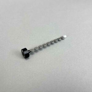
BUBBLE PADDLE RESERVOIR, Magnetic Clutch Powered, 96 Channel, PTFE Reservoir, Sculpted Bottom, Overflow Weir and Inlet, with 6 Bubble Paddles, Parylene Coated, 9 Bubbles/Paddle, Mates to VP 765B, Mixes 210mL, SLAS Footprint

Drive System

Magnetic Clutch

Pipette Head Format

96

Material

PTFE

No of Bubble Paddles

6

Bubbles/Paddle

9

Encapsulation/Coating

Parylene C Coated

Volume

210mL

SLAS Base

Yes

No of Channels

96

Particulate Magnetic Clutch Suspension Systems in Reservoirs – Many Choices

V&P has developed over 30 different reservoir suspension systems for pipetting uniformly suspended beads, cells, particles, and resins into microplates of nearly every description. We have refined, perfected, and consolidated that list down to the best 26. These reservoir suspension systems are powered by motors spinning magnetic clutches and connecting through the reservoir wall to a corresponding magnetic clutch attached to one or more of our Bubble Paddles. This magnetic clutch system eliminates the need for a sealed bearing connecting the motor to the Bubble Paddle. The Magnetic clutch system works for all particulates except magnetic beads as the magnetic beads are attracted to the magnets in the clutches.

Uniformity of Suspension and Small Dead Volumes are Important

Keeping assay beads, SPA beads, glass beads, resins other particulates, and cells in homogeneous suspension while they are being pipetted to microplate wells is very important if reproducible results are to be obtained. It is also important to do this with the smallest dead volume possible when the reagents are very expensive.

The unique V&P Scientific Bubble Paddle Reservoir suspension systems (US Patent #6,461,034 & European Union Patent #1,314,471) provide a very simple and inexpensive way of accomplishing this goal. Whether you are using a 4, 8, 16, 24, 96, or 384 pipetting head, there is a magnetic clutch suspension reservoir with bubble spacing that allows a pipet tip to be inserted in the gap between bubbles. The unique contours machined into the reservoir coupled with the contours of the Bubble Paddle design results in a very vigorous upwelling current resulting in a homogeneous suspension of the particulate contents in the reservoir. The unique feature of the Bubble Paddle Reservoirs is their exclusive design that eliminates “fall out zones” where particulates fall out of solution that is so prevalent with other mixing reservoirs. Also if dead volume is not an issue in your assay you can use our economical VP 756C-1PTFE  suspension reservoir powered by a  VP 761-3 Magnetic Clutch Drive Motor in conjunction with a 4, 8, or 16 pipet head for a low-cost reservoir suspension system.

Match the Particulate and Application to the Appropriate Suspension Reservoir System

There are many characteristics of your material that will affect where and how they are suspended:

  • The size of the material – is it larger than the paddle/reservoir contour gap
  • The density of the material
  • The fragility of the material
  • The speed at which it can be stirred without breakage
  • The temperature sensitivity of the material
  • The light sensitivity of the material
  • Does the reservoir need to be continuously fed


All of the above features are very important, and we have dealt with all of them over the course of the last 16 years that is why we say “choose your suspension system wisely before you launch a new assay protocol”.  With our large selection of Suspension Reservoirs Systems, we can help you make the best decision for your application.  We are happy to share our knowledge with you. We may be able to suggest a specific product for your application. If economy and uniformity of suspension are important to you, we have solutions for you.

Advantages of V&P Scientific’s Magnetic Clutch Suspension Reservoir Systems
  • V&P’s patented contours in the bottom of the reservoir which match the contours of the Bubble Paddles produce a vigorous upwelling current in the reservoirs to keep particulates in uniform suspension
  • The Bubble Paddles are contoured so pipet tips will fit in the gaps between the bubbles and not interfere with spinning bubble paddles
  • V&P’s patented contours in the bottom design also eliminate “fall out zones” where particulates settle out in other mixing reservoirs
  • Small footprint on Robot Deck, because it doesn’t require a large Tumble Stirrer to power the Bubble Paddles
  • Designed to fit on robot deck features to facilitate precise x and y matching to the robot pipetting system
  • Designed to be taken off the robot deck and replaced in the exact same position
  • Greatest variety of Suspension Reservoirs Systems for 1, 4, 8, 12, 16, 24, 96, and 384 pipettors
  • Multiple versions of Suspension Reservoirs Systems for different volumes and applications
  • Available in chemical-resistant materials (PTFE, Delrin, Polypropylene)
  • Available in light blocking materials (Black Delrin)
  • Available in autoclavable or chemically sterilizable materials
  • Available in versions for heating or chilling the contents of the reservoir
  • Low dead volume designs to conserve expensive reagents
  • Capable of continuous refilling for long run times
  • Custom Suspension Reservoir Systems, not a problem
  • Flexibility is our specialty

V&P Scientific’s Patented Magnetic Clutch Suspension Reservoir System Applications

Keep any non-magnetic particulate in homogeneous suspension for pipetting of equal particle quantities into microplates or vials.  There’s an endless amount of possible applications.

Stir and suspend any particulate in any solution.

  • Beads
  • Glass Beads (YSi Beads)
  • Gold Beads
  • Nano Beads
  • Cellulose Nanobeads
  • Sepharose Beads
  • Agarose Beads
  • Latex Beads
  • Resins
  • Polymeric Microbeads
  • Mammalian cells
  • Bacterial cells
  • Fungal cells
  • Viruses
  • Quantum-dot nanocrystals

Our Magnetic Clutch Suspension Reservoir Systems accommodate many pipetting robots and can also be used on the bench top with manual with either single, 8 and 12 channel pipets.

Robotic Pipetting systems with x pipets:

  • 1
  • 4
  • 8
  • 12
  • 16
  • 24
  • 96
  • 384

Our specialized Magnetic Clutch Suspension Reservoir Systems can be used in a variety of different environments, and with unique liquids.

  • Sterile liquids
  • Heated liquids
  • Cooled liquids
  • Light sensitive reagents
  • Organic solvents
  • Viscous liquids
  • Fragile particulates

109 Magnetic Clutch 96 Bubble Paddle Reservoir 6 paddle

Related Products

15% OFF
Year End Discount on SpinVessel®️ Consumables
View Sale

Hydrophobic Coated vs Non-Coated Pin Transfers

Solid Pin Delivery Data For Aqueous Solutions In 96 Format With Uncoated And /Ah Hydrophobic Coated Pins
PinDescriptionnl TransferredCV%
0.229 mm diameter (FP9)Total PinUncoated7.412.4
Hydrophobic7.465.4
0.229 mm diameter (FP9)Hanging DropUncoatedN/AN/A
Hydrophobic2.093.8
0.457 mm diameter (FP1)Total PinUncoated33.483.2
Hydrophobic28.177.5
0.457 mm diameter (FP1)Hanging DropUncoated16.964.5
Hydrophobic8.510.8
0.787 mm diameter (FP3)Total PinUncoated87.323.9
Hydrophobic77.43.9
0.787 mm diameter (FP3)Hanging DropUncoated48.771.2
Hydrophobic43.059.4
1.19 mm diameter  (VP 409 & VP 386)Total PinUncoated247.222.8
Hydrophobic192.672.6
1.19 mm diameter (VP 409 & VP 386)Hanging DropUncoated76.351.6
Hydrophobic108.42.8
1.58 mm diameter (VP 408 & VP 384)Total PinUncoated273.54.6
Hydrophobic259.253.1
1.58 mm diameter (VP 408 & VP 384)Hanging DropUncoated201.935
Hydrophobic170.047.5

Transfer Of Horseradish Peroxidase In Tris Buffered Saline With Pin Tools

Conclusion

Coating pins will reduce the total amount of liquid transferred and also reduce the amount of non-specific binding to the stainless-steel pins. If the substance you are transferring has high non-specific binding this will be an important factor in selecting your pins.

Slot Pin Delivery Data For Aqueous Solutions In 96 Format With Uncoated And /Ah Hydrophobic Coated Pin
PinDescriptionnl TransferredCV%
0.229 mm diameter (FP9)Total PinUncoated7.412.4
Hydrophobic7.465.4
0.229 mm diameter (FP9)Hanging DropUncoatedN/AN/A
Hydrophobic2.093.8
0.457 mm diameter (FP1)Total PinUncoated33.483.2
Hydrophobic28.177.5
0.457 mm diameter (FP1)Hanging DropUncoated16.964.5
Hydrophobic8.510.8
0.787 mm diameter (FP3)Total PinUncoated87.323.9
Hydrophobic77.43.9
0.787 mm diameter (FP3)Hanging DropUncoated48.771.2
Hydrophobic43.059.4
1.19 mm diameter  (VP 409 & VP 386)Total PinUncoated247.222.8
Hydrophobic192.672.6
1.19 mm diameter (VP 409 & VP 386)Hanging DropUncoated76.351.6
Hydrophobic108.42.8
1.58 mm diameter (VP 408 & VP 384)Total PinUncoated273.54.6
Hydrophobic259.253.1
1.58 mm diameter (VP 408 & VP 384)Hanging DropUncoated201.935
Hydrophobic170.047.5

Transfer Of Horseradish Peroxidase In Tris Buffered Saline With Pin Tools

Conclusion

Although the slots in the pin are a precise volume, the liquid that is transferred is usually more. The reason for this is due to the surface tension of the liquid causing the liquid in the slot to “bow out” thus increasing the volume of the liquid in the slot. If is important for you to transfer exactly a certain volume we can make custom slots to match the surface tension characteristics of your liquid

Liquid Surface Tension

Effect Of DNA Or BSA Concentration On Slot Pin Transfers Of Uncoated And Hydrophobic Coated Pins (FP3CS500)
Solvent/SampleConcentrationCV%nl FITC TransferredCV%nl FITC Transferred
UncoatedUncoatedHydrophobic CoatedHydrophobic Coated
DMSO (-)08.1353.427.5298.72
DMSO + DNA (mg/ml)0.56.6497.216.6435.86
0.259432.494.1391.93
0.1258.9363.640.9344.75
0.06252.3381.862331.68
0.03131.5378.034.4331.71
0.01561.2357.521.4329.03
Tris (-)04.9577.317.2493.53
Tris + DNA (mg/ml)0.54.5540.531.1477.5
0.254.6518.216.1456.75
0.12515.8583.254.1438.82
0.06254.2551.173.1433.69
0.03134.4536.662.3458.37
0.01562.9528.531.2441.1
Tris + BSA (%)45.4462.1311409.27
14452.862.7426.58
0.2511.7456.451.3408.72
0.06251.1445.226.5393.07
0.01563.7462.853.9430.2
0.00391.5493.542.2437.29
0.0012.9504.250.7475.96
Conclusions

1. Increasing the concentration of DNA (sheared salmon sperm) to .25 mg/ml significantly increases the volume of DMSO liquid transferred for both coated and uncoated FP3S500 Slot Pins.
2. Increasing the concentration of DNA does not significantly increase the volume of Tris buffer (aqueous) transferred by both coated and uncoated FP3S500 Slot Pins.
3. Increasing the concentration of BSA (Bovine Serum Albumin) significantly decreases the volume of Tris buffer transferred by both coated and uncoated FP3S500 Slot Pins.
4. Hydrophobic coated FP3S500 Slot Pins transferred less DMSO – DNA and less Tris DNA and less Tris BSA than the uncoated FP3S500 Slot Pins.
5. Both coated and uncoated FP3S500 pins transfer significantly more aqueous solution than DMSO.

Effect Of DNA Or BSA Concentration On Slot Pin Transfers Of Uncoated And Hydrophobic Coated Pins (FP1CS50)
Solvent/SampleConcentrationCV%nl FITC TransferredCV%nl FITC Transferred
UncoatedUncoatedHydrophobic CoatedHydrophobic Coated
DMSO (-)04.249.382.149.31
DMSO + DNA (mg/ml)0.54.951.242.656.79
0.251.750.21.249.53
0.1251.551.272.349.77
0.06252.249.344.148.19
0.03131.249.030.250.23
0.01562.445.91.446.64
Tris (-)02.689.512.991.34
Tris + DNA (mg/ml)0.5777.110.684.62
0.253.982.221.684.89
0.1253.985.42185.08
0.06251.585.362.885.03
0.0313284.52388.19
0.01562.682.922.883.2
Conclusions

1. In contrast to the FP3S500 data, increasing the concentration of DNA to .25 mg/ml does not significantly increase the volume of DMSO liquid transferred for both coated and uncoated FP1S50 Slot Pins.
2. Increasing the concentration of DNA does not significantly increase the volume of Tris buffer (aqueous) transferred by both coated and uncoated FP1S50 Slot Pins.
3. In contrast to the FP3S500 data, FP1S50 coated pins transferred about the same volume of DNA at all concentrations as did uncoated pins.
4. Both coated and uncoated FP1S50 pins transfer significantly more aqueous solution than DMSO.
5. The differences between the FP3S500 and the FP1S50 pin may be due to the different pin diameter’s effect on contact angle and therefore on the “wetting” of the pin. See the diagram on the link to / ah energy system.

PinDescriptionnl TransferredCV%
0.229 mm diameter (FP9)Total PinUncoated7.412.4
Hydrophobic7.465.4
0.229 mm diameter (FP9)Hanging DropUncoatedN/AN/A
Hydrophobic2.093.8
0.457 mm diameter (FP1)Total PinUncoated33.483.2
Hydrophobic28.177.5
0.457 mm diameter (FP1)Hanging DropUncoated16.964.5
Hydrophobic8.510.8
0.787 mm diameter (FP3)Total PinUncoated87.323.9
Hydrophobic77.43.9
0.787 mm diameter (FP3)Hanging DropUncoated48.771.2
Hydrophobic43.059.4
1.19 mm diameter  (VP 409 & VP 386)Total PinUncoated247.222.8
Hydrophobic192.672.6
1.19 mm diameter (VP 409 & VP 386)Hanging DropUncoated76.351.6
Hydrophobic108.42.8
1.58 mm diameter (VP 408 & VP 384)Total PinUncoated273.54.6
Hydrophobic259.253.1
1.58 mm diameter (VP 408 & VP 384)Hanging DropUncoated201.935
Hydrophobic170.047.5

Aqueous Transfer with Solid Pins

Hydrophobic coating pins will reduce the total amount of aqueous HRP liquid transferred and also reduce the amount of non-specific binding to the stainless-steel pins. If the substance you are transferring has high non-specific binding this will be an important factor in selecting your pins.


Pin diameter also has an effect on the degree of reduction of liquid transfer with hydrophobic coating as the smaller the diameter the less the reduction of transfer. This is most likely due to the curvature of the pin affecting the wetting contact angle

PinDescriptionnl TransferredCV%
0.457 mm diameter (FP1)6 nl SlotTotal Pin*Uncoated25.610.8
HydrophobicN/AN/A
10 nl SlotTotal Pin*Uncoated23.366.1
Hydrophobic25.856.9
50 nl SlotTotal Pin*Uncoated67.832.5
HydrophobicN/AN/A
0.787 mm diameter (FP3)  100 nl SlotTotal Pin*Uncoated180.327.2
Hydrophobic205.845.5
200 nl SlotTotal Pin*Uncoated277.824.9
Hydrophobic287.33.8
500 nl SlotTotal Pin*Uncoated581.165.2
Hydrophobic555.693

DMSO Transfer with Slot Pins

Hydrophobic coating pins will slightly increase the total amount of DMSO FITC liquid transferred.

PinDescriptionnl TransferredCV%
0.787 mm diameter (FP3)    100 nl Slot Total Pin, Including SlotUncoated195.691.6
Hydrophobic170.22.9
0.787 mm diameter (FP3)  100 nl Slot, Slot OnlyUncoated149.674.9
Hydrophobic129.617.6
0.787 mm diameter (FP3)200 nl Slot Total Pin, Including SlotUncoated269.771.9
Hydrophobic228.6217.1
0.787 mm diameter (FP3)200 nl Slot, Slot OnlyUncoated237.528.9
Hydrophobic186.95.9

Aqueous Transfer with Slot Pins

Although the slots in the pin are a precise volume, the liquid that is transferred is usually more because of the volume carried on the sides of the pins. 

As seen with other aqueous data the amount transferred on hydrophobic coated Slot pins is less than on uncoated Solid or Slot pins. Thus Hydrophobic coating has the most effect on aqueous transfers.

Withdrawl Speeds Impact on Volume Transfer

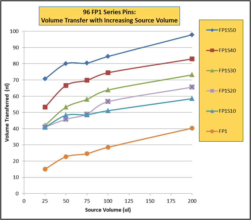
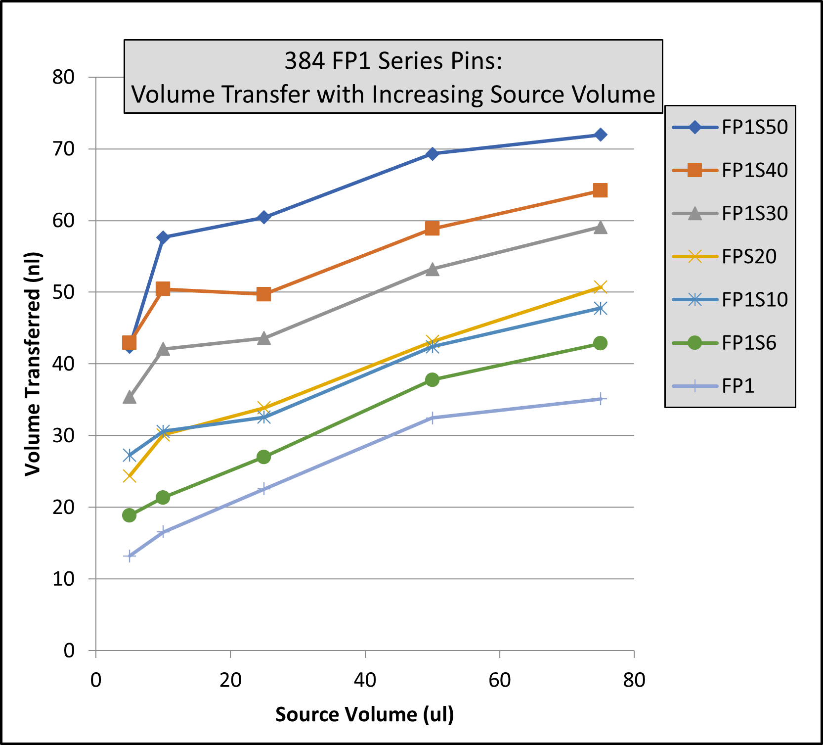
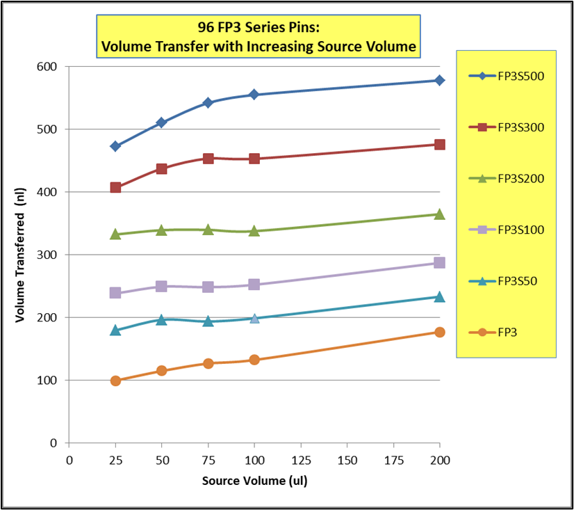
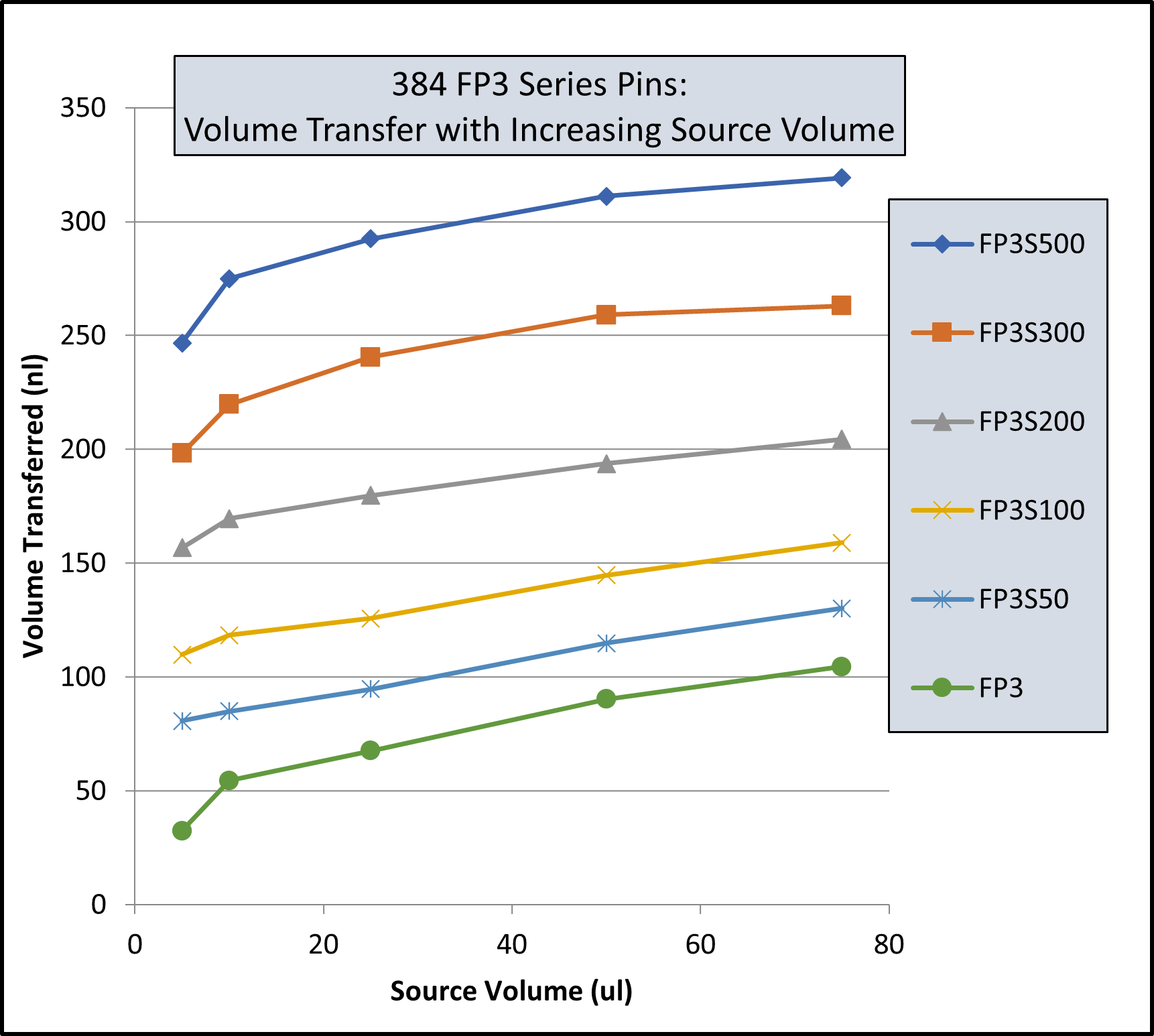
Solid Pins More affected by Source Plate Volume

Volume Transferred For FP1 Pins (Uncoated) In 96 And 384 Formats
Volume Transferred For FP3 Pins (Uncoated) In 96 And 384 Formats

Note: Same volume (200ul for 96 Format and 74 ul for 384 Format) in recipient plates and same pin withdrawal speed for all pins. Changes to pin withdrawal speed or volume in the source plate can result in different volumes being transferred.

Transfer volumes should always be confirmed by customers for their assay conditions and automated system.

Aqueous Solutions Pin Transfer Volumes Ranges

Aqueous Solutions on Uncoated Pins in 96 Format Microplates(1)
Pin TypePin Diameter(mm)Shape96 Format Low Range(nL)²96 Format High Range(nL)²
FP90.229Solid1339
FP80.356Solid1537
FP10.457Solid2261
FP1S60.4576nL Slot3467
FP1S100.45710nL Slot3974
FP1S500.45750nL Slot90124
FP30.787Solid93213
FP3S1000.787100nL Slot213334
FP3S2000.787200nL Slot311449
FP3S5000.787500nL Slot515671
FP40.914Solid126289
Footnotes: (1) Delivery volume range is determined by speed of withdrawal from source liquid: Z-Speed Range = 1.5-30 mm/sec, slow speed = low volume delivery range, fast speed = high volume delivery range (2) 200ul source plate volume per well
Aqueous Solutions on Hydrophobic Pins in 96 Format Microplates(1)
Pin TypePin Diameter(mm)Shape96 Format Low Range(nL)²96 Format High Range(nL)²
FP90.229Solid1338
FP80.356Solid
FP10.457Solid2360
FP1S60.4576nL Slot3367
FP1S100.45710nL Slot4075
FP1S500.45750nL Slot86119
FP30.787Solid76209
FP3S1000.787100nL Slot188324
FP3S2000.787200nL Slot288436
FP3S5000.787500nL Slot473649
FP40.914Solid
Footnotes: (1) Delivery volume range is determined by speed of withdrawal from source liquid: Z-Speed Range = 1.5-30 mm/sec, slow speed = low volume delivery range, fast speed = high volume delivery range (2) 200ul source plate volume per well
Aqueous Solution on E-Clip, Uncoated Pins(1)
Pin TypePin Diameter(mm)ShapeLow Range(nL)²High Range(nL)²
FP1.58Solid Pointed175594
FPS.51.58500nL Slot524962
FPS1.581000nL Slot10561476
FPS21.582000nL Slot17392174
FPS51.585000nL Slot51504953
FP61.58Solid Flat465960
FP6S.51.58500nL Slot9341445
FP6S1.581000nL Slot13961930
FP6S21.582000nL Slot20722637
FP6S51.585000nL Slot48204693
Footnotes:(1) Delivery volume range is determined by speed of withdrawal from source liquid: Z-Speed Range = 1.5-30 mm/sec, slow speed = low volume delivery range, fast speed = high volume delivery range (2) 200ul source plate volume per well for 96 Format and 75ul source plate volume per well for 384 Format

DMSO Pin Transfer Volume Range Charts

Uncoated Pins in 96 and 384 Format Microplates(1)
Pin TypePin Diameter(mm)Shape96 Format Low Range(nL)²96 Format High Range(nL)²384 Format Low Range(nL)³384 Format High Range(nL)³
FP90.229Solid41038
FP80.35Solid1326618
FP10.457Solid18431131
FP1S60.4576nL Slot24491534
FP1S100.45710nL Slot30542140
FP1S200.45720nL Slot37612746
FP1S300.45730nL Slot46683554
FP1S400.45740nL Slot57784563
FP1S500.45750nL Slot70905675
FP30.787Solid671392979
FP40.91Solid941973498
FP3S1000.787100nL Slot175241114163
FP3S2000.787200nL Slot280332203250
FP3S5000.787500nL Slot535559427464
FP4S10000.911000nL Slot9401011704800
FP4S20000.912000nL Slot1518160812771362
Footnotes: (1) Delivery volume range is determined by speed of withdrawal from source liquid: Z-Speed Range = 1.5-30 mm/sec, slow speed = low volume delivery range, fast speed = high volume delivery range (2) 200ul source plate volume per well (3) 75ul source plate volume per well
Hydrophobic-coated Pins in 96 and 384 Format Microplates(1)
Pin TypePin Diameter (mm)Shape96 Format Low Range(nL)²96 Format High Range(nL)²384 Format Low Range(nL)³384 Format High Range(nL)³
FP9H0.229Solid41038
FP8H0.35Solid924617
FP1H0.457Solid1539927
FP1S6H0.4576nL Slot23491432
FP1S10H0.45710nL Slot29532038
FP1S20H0.45720nL Slot35592643
FP1S30H0.45730nL Slot47693553
FP1S40H0.45740nL Slot54754158
FP1S50H0.45750nL Slot69905773
FP3H0.787Solid671342776
FP4H0.91Solid9518932102
FP3S100H0.787100nL Slot170227108164
FP3S200H0.787200nL Slot266320190239
FP3S500H0.787500nL Slot520542416456
FP4S1000H0.911000nL Slot9321000741805
FP4S2000H0.912000nL Slot1571163813511423
Footnotes: (1) Delivery volume range is determined by speed of withdrawal from source liquid: Z-Speed Range = 1.5-30 mm/sec, slow speed = low volume delivery range, fast speed = high volume delivery range (2) 200ul source plate volume per well (3) 75ul source plate volume per well
E-Clip, Uncoated Pins, for 96 and 384 Format Microplates(1)
Pin TypeDiameter (mm)Shape96 Format Low Range(nL)²96 Format High Range(nL)²384 Format Low Range(nL)³384 Format High Range(nL)³
FP1.58Solid Pointed147411168395
FPS.51.58500nL Slot442704631843
FPS1.581000nL Slot893113013431498
FPS21.582000nL Slot1911203826072767
FPS51.585000nL Slot3908429651805253
FP61.58Solid Flat323674154398
FP6S.51.58500nL Slot73410428551053
FP6S1.581000nL Slot1210150016381717
FP6S21.582000nL Slot2299238427873068
FP6S51.585000nL Slot4329465652375245
Footnotes:(1) Delivery volume range is determined by speed of withdrawal from source liquid: Z-Speed Range = 1.5-30 mm/sec, slow speed = low volume delivery range, fast speed = high volume delivery range (2) 200ul source plate volume per well (3) 75ul source plate volume per well