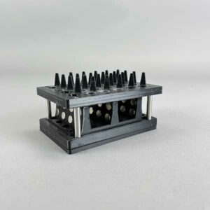
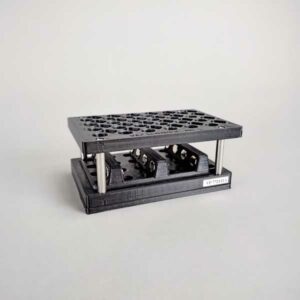
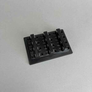
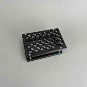
MAGNETIC BEAD SEPARATION RACK, Top Rack of the VP 772F11A-HV, 24 Flip Top Microcentrifuge Tubes, 1.5mL or 2.0mL Volume, Low Position, 18mm Center Spacing in X, 19mm Center Spacing in Y, 11.1mm Hole Diameter, PLA
MAGNETIC BEAD SEPARATION RACK, Top Rack of the VP 772F11A-HV, 24 Flip Top Microcentrifuge Tubes, 1.5mL or 2.0mL Volume
MAGNETIC BEAD SEPARATION RACK, Top Rack of the VP 772F11A-HV, 24 Flip Top Microcentrifuge Tubes, 1.5mL or 2.0mL Volume, Low Position, 18mm Center Spacing in X, 19mm Center Spacing in Y, 11.1mm Hole Diameter, PLA
Material | PLA |
---|---|
Volume | 0.2mL, 0.5mL |
No of Tubes | 24 |
V&P has developed over 37 different Magnetic Bead Separation Racks and devices for bottles, tubes, and micro-tubes, of nearly every description and covering the following range of rack size and vessel size.
It is important to match the right magnetic bead separation device with your particular bottle or tube. There are many characteristics of bottles and tubes that will affect where and how tightly the magnetic beads are pelleted:
All of the above features are very important, and we have dealt with all of them over the course of the last 10 years that is why we say “choose your bottle or tube wisely before you launch a new assay protocol”. With our large selection of magnetic separation devices, we can help you make the best decision for your application. We are happy to share our knowledge with you.
We also consider the magnetic beads or particles you are using:
We may be able to suggest a specific product for your application. If the speed of separation is important to you, larger magnetic bead particles with greater magnetic moment will separate faster rather than weaker smaller particles.
Depending on your protocol, you may want the beads to be collected:
The magnetic field orientation of adjacent magnets has a force multiplying effect (Halbach effect) and results in the magnetic beads being more tightly held:
More commonly, magnetic beads are separated by aspiration using pipet tips and then washed. By using pipet tips, it is important to keep the beads away from the pipet. This is why bead pellet location and how tightly it is magnetically held are so important. Similar consideration also applies to needle aspiration used in automatic plate washers.
V&P Scientific was the first to develop the Flick and Blot system for removing supernatant solutions from magnetic bead pellets. These devices allow for the microplate to be fixed to the magnet plate. You can then pick up the entire device and “Flick” out the supernatant into a sink or other container. This is a fast, economical way of removing a non-toxic supernatant from your microplates while still retaining your magnetic beads in the microplate for more rounds of washing.
Recently V&P Scientific developed a different method to separate the supernatant from the magnetic beads by using a 96 magnetic pin replicator (VP 407AM-N1) that is submerged into the wells and will remove the beads from the microplate and leave the supernatant behind in the microplate. Using a PCR plate as a shield, you can use our handheld magnetic pin tool device to move the beads from one microplate to another. This will save you time as it only takes a few seconds. It will also save you money as no expensive pipet tips are needed, all you need is an inexpensive PCR plate.
See our accessories for aspirating supernatants, adding wash solutions, and for keeping magnetic beads uniformly in suspension prior to adding to microplate wells. Recently we have developed a new SpinVesselTM method that keeps magnetic beads in uniform suspension for aliquoting into microplates.
Since the introduction of Magnetic Beads as a method to separate bound from unbound ligands the applications and variation of Magnetic Bead Assays has soared exponentially, and they are literally too numerous to count. Magnetic Bead Separation Assays have rapidly replaced the slower and more cumbersome techniques of absorption (ELISA), centrifugation, and filtration separation methods. In addition, Magnetic Bead assays have increased the recovery of the sample and its purity with fewer wash steps.
Magnetic Beads have been successfully coupled to antibodies, antigens, proteins, viruses, bacteria, fungi, Ligands, DNA, RNA, Avidin, Streptavidin, Biotin, staphylococcal protein A and the list goes on…. Furthermore, these Magnetic beads have also been directly labeled with radioisotopes, enzymes, dyes, fluorescent compounds, and complementary metal oxide semiconductors (CMOS) and quantum dots (QD) for direct detection with biosensors resulting in even more capability and multiplexing opportunities.
This said Magnetic Bead Separation assays are the clear and obvious method of choice for the foreseeable future. V&P Scientific will work with developers of new Magnetic Bead assays to provide the perfect Magnetic Bead Separation device. We have already developed over 100 devices and perfected 72 different Magnetic Bead Separation devices for microplates and 29 for micro-tubes, test tubes, and bottles. Many of these are sold on an OEM basis to both diagnostic companies and plate washing companies.
List of Applications for our Magnetic Bead Separation Blocks or Racks
We have also developed new devices for keeping magnetic beads in uniform suspension while being pipetted into microplates. See our new SpinVessel® System for dispensing uniform suspensions of magnetic beads which has the advantage of operating with larger total volumes of magnetic beads and yet leave very little dead volume in the vessel. We have also recently developed a new MagWash® System for washing Magnetic beads or concentrating dilute analytes.
See our older Sealed Bearing Magnetic Bead Suspension Reservoirs and Tumble Stirrer Magnetic Bead Suspension Reservoirs.
Pin | Description | nl Transferred | CV% | |
---|---|---|---|---|
0.229 mm diameter (FP9) | Total Pin | Uncoated | 7.41 | 2.4 |
Hydrophobic | 7.46 | 5.4 | ||
0.229 mm diameter (FP9) | Hanging Drop | Uncoated | N/A | N/A |
Hydrophobic | 2.09 | 3.8 | ||
0.457 mm diameter (FP1) | Total Pin | Uncoated | 33.48 | 3.2 |
Hydrophobic | 28.17 | 7.5 | ||
0.457 mm diameter (FP1) | Hanging Drop | Uncoated | 16.96 | 4.5 |
Hydrophobic | 8.51 | 0.8 | ||
0.787 mm diameter (FP3) | Total Pin | Uncoated | 87.32 | 3.9 |
Hydrophobic | 77.4 | 3.9 | ||
0.787 mm diameter (FP3) | Hanging Drop | Uncoated | 48.77 | 1.2 |
Hydrophobic | 43.05 | 9.4 | ||
1.19 mm diameter (VP 409 & VP 386) | Total Pin | Uncoated | 247.22 | 2.8 |
Hydrophobic | 192.67 | 2.6 | ||
1.19 mm diameter (VP 409 & VP 386) | Hanging Drop | Uncoated | 76.35 | 1.6 |
Hydrophobic | 108.4 | 2.8 | ||
1.58 mm diameter (VP 408 & VP 384) | Total Pin | Uncoated | 273.5 | 4.6 |
Hydrophobic | 259.25 | 3.1 | ||
1.58 mm diameter (VP 408 & VP 384) | Hanging Drop | Uncoated | 201.93 | 5 |
Hydrophobic | 170.04 | 7.5 |
Transfer Of Horseradish Peroxidase In Tris Buffered Saline With Pin Tools
Coating pins will reduce the total amount of liquid transferred and also reduce the amount of non-specific binding to the stainless-steel pins. If the substance you are transferring has high non-specific binding this will be an important factor in selecting your pins.
Pin | Description | nl Transferred | CV% | |
---|---|---|---|---|
0.229 mm diameter (FP9) | Total Pin | Uncoated | 7.41 | 2.4 |
Hydrophobic | 7.46 | 5.4 | ||
0.229 mm diameter (FP9) | Hanging Drop | Uncoated | N/A | N/A |
Hydrophobic | 2.09 | 3.8 | ||
0.457 mm diameter (FP1) | Total Pin | Uncoated | 33.48 | 3.2 |
Hydrophobic | 28.17 | 7.5 | ||
0.457 mm diameter (FP1) | Hanging Drop | Uncoated | 16.96 | 4.5 |
Hydrophobic | 8.51 | 0.8 | ||
0.787 mm diameter (FP3) | Total Pin | Uncoated | 87.32 | 3.9 |
Hydrophobic | 77.4 | 3.9 | ||
0.787 mm diameter (FP3) | Hanging Drop | Uncoated | 48.77 | 1.2 |
Hydrophobic | 43.05 | 9.4 | ||
1.19 mm diameter (VP 409 & VP 386) | Total Pin | Uncoated | 247.22 | 2.8 |
Hydrophobic | 192.67 | 2.6 | ||
1.19 mm diameter (VP 409 & VP 386) | Hanging Drop | Uncoated | 76.35 | 1.6 |
Hydrophobic | 108.4 | 2.8 | ||
1.58 mm diameter (VP 408 & VP 384) | Total Pin | Uncoated | 273.5 | 4.6 |
Hydrophobic | 259.25 | 3.1 | ||
1.58 mm diameter (VP 408 & VP 384) | Hanging Drop | Uncoated | 201.93 | 5 |
Hydrophobic | 170.04 | 7.5 |
Transfer Of Horseradish Peroxidase In Tris Buffered Saline With Pin Tools
Although the slots in the pin are a precise volume, the liquid that is transferred is usually more. The reason for this is due to the surface tension of the liquid causing the liquid in the slot to “bow out” thus increasing the volume of the liquid in the slot. If is important for you to transfer exactly a certain volume we can make custom slots to match the surface tension characteristics of your liquid
Solvent/Sample | Concentration | CV% | nl FITC Transferred | CV% | nl FITC Transferred |
---|---|---|---|---|---|
Uncoated | Uncoated | Hydrophobic Coated | Hydrophobic Coated | ||
DMSO (-) | 0 | 8.1 | 353.42 | 7.5 | 298.72 |
DMSO + DNA (mg/ml) | 0.5 | 6.6 | 497.21 | 6.6 | 435.86 |
0.25 | 9 | 432.49 | 4.1 | 391.93 | |
0.125 | 8.9 | 363.64 | 0.9 | 344.75 | |
0.0625 | 2.3 | 381.86 | 2 | 331.68 | |
0.0313 | 1.5 | 378.03 | 4.4 | 331.71 | |
0.0156 | 1.2 | 357.52 | 1.4 | 329.03 | |
Tris (-) | 0 | 4.9 | 577.31 | 7.2 | 493.53 |
Tris + DNA (mg/ml) | 0.5 | 4.5 | 540.53 | 1.1 | 477.5 |
0.25 | 4.6 | 518.21 | 6.1 | 456.75 | |
0.125 | 15.8 | 583.25 | 4.1 | 438.82 | |
0.0625 | 4.2 | 551.17 | 3.1 | 433.69 | |
0.0313 | 4.4 | 536.66 | 2.3 | 458.37 | |
0.0156 | 2.9 | 528.53 | 1.2 | 441.1 | |
Tris + BSA (%) | 4 | 5.4 | 462.13 | 11 | 409.27 |
1 | 4 | 452.86 | 2.7 | 426.58 | |
0.25 | 11.7 | 456.45 | 1.3 | 408.72 | |
0.0625 | 1.1 | 445.22 | 6.5 | 393.07 | |
0.0156 | 3.7 | 462.85 | 3.9 | 430.2 | |
0.0039 | 1.5 | 493.54 | 2.2 | 437.29 | |
0.001 | 2.9 | 504.25 | 0.7 | 475.96 |
1. Increasing the concentration of DNA (sheared salmon sperm) to .25 mg/ml significantly increases the volume of DMSO liquid transferred for both coated and uncoated FP3S500 Slot Pins.
2. Increasing the concentration of DNA does not significantly increase the volume of Tris buffer (aqueous) transferred by both coated and uncoated FP3S500 Slot Pins.
3. Increasing the concentration of BSA (Bovine Serum Albumin) significantly decreases the volume of Tris buffer transferred by both coated and uncoated FP3S500 Slot Pins.
4. Hydrophobic coated FP3S500 Slot Pins transferred less DMSO – DNA and less Tris DNA and less Tris BSA than the uncoated FP3S500 Slot Pins.
5. Both coated and uncoated FP3S500 pins transfer significantly more aqueous solution than DMSO.
Solvent/Sample | Concentration | CV% | nl FITC Transferred | CV% | nl FITC Transferred |
---|---|---|---|---|---|
Uncoated | Uncoated | Hydrophobic Coated | Hydrophobic Coated | ||
DMSO (-) | 0 | 4.2 | 49.38 | 2.1 | 49.31 |
DMSO + DNA (mg/ml) | 0.5 | 4.9 | 51.24 | 2.6 | 56.79 |
0.25 | 1.7 | 50.2 | 1.2 | 49.53 | |
0.125 | 1.5 | 51.27 | 2.3 | 49.77 | |
0.0625 | 2.2 | 49.34 | 4.1 | 48.19 | |
0.0313 | 1.2 | 49.03 | 0.2 | 50.23 | |
0.0156 | 2.4 | 45.9 | 1.4 | 46.64 | |
Tris (-) | 0 | 2.6 | 89.51 | 2.9 | 91.34 |
Tris + DNA (mg/ml) | 0.5 | 7 | 77.11 | 0.6 | 84.62 |
0.25 | 3.9 | 82.22 | 1.6 | 84.89 | |
0.125 | 3.9 | 85.42 | 1 | 85.08 | |
0.0625 | 1.5 | 85.36 | 2.8 | 85.03 | |
0.0313 | 2 | 84.52 | 3 | 88.19 | |
0.0156 | 2.6 | 82.92 | 2.8 | 83.2 |
1. In contrast to the FP3S500 data, increasing the concentration of DNA to .25 mg/ml does not significantly increase the volume of DMSO liquid transferred for both coated and uncoated FP1S50 Slot Pins.
2. Increasing the concentration of DNA does not significantly increase the volume of Tris buffer (aqueous) transferred by both coated and uncoated FP1S50 Slot Pins.
3. In contrast to the FP3S500 data, FP1S50 coated pins transferred about the same volume of DNA at all concentrations as did uncoated pins.
4. Both coated and uncoated FP1S50 pins transfer significantly more aqueous solution than DMSO.
5. The differences between the FP3S500 and the FP1S50 pin may be due to the different pin diameter’s effect on contact angle and therefore on the “wetting” of the pin. See the diagram on the link to / ah energy system.
Pin | Description | nl Transferred | CV% | |
---|---|---|---|---|
0.229 mm diameter (FP9) | Total Pin | Uncoated | 7.41 | 2.4 |
Hydrophobic | 7.46 | 5.4 | ||
0.229 mm diameter (FP9) | Hanging Drop | Uncoated | N/A | N/A |
Hydrophobic | 2.09 | 3.8 | ||
0.457 mm diameter (FP1) | Total Pin | Uncoated | 33.48 | 3.2 |
Hydrophobic | 28.17 | 7.5 | ||
0.457 mm diameter (FP1) | Hanging Drop | Uncoated | 16.96 | 4.5 |
Hydrophobic | 8.51 | 0.8 | ||
0.787 mm diameter (FP3) | Total Pin | Uncoated | 87.32 | 3.9 |
Hydrophobic | 77.4 | 3.9 | ||
0.787 mm diameter (FP3) | Hanging Drop | Uncoated | 48.77 | 1.2 |
Hydrophobic | 43.05 | 9.4 | ||
1.19 mm diameter (VP 409 & VP 386) | Total Pin | Uncoated | 247.22 | 2.8 |
Hydrophobic | 192.67 | 2.6 | ||
1.19 mm diameter (VP 409 & VP 386) | Hanging Drop | Uncoated | 76.35 | 1.6 |
Hydrophobic | 108.4 | 2.8 | ||
1.58 mm diameter (VP 408 & VP 384) | Total Pin | Uncoated | 273.5 | 4.6 |
Hydrophobic | 259.25 | 3.1 | ||
1.58 mm diameter (VP 408 & VP 384) | Hanging Drop | Uncoated | 201.93 | 5 |
Hydrophobic | 170.04 | 7.5 |
Hydrophobic coating pins will reduce the total amount of aqueous HRP liquid transferred and also reduce the amount of non-specific binding to the stainless-steel pins. If the substance you are transferring has high non-specific binding this will be an important factor in selecting your pins.
Pin diameter also has an effect on the degree of reduction of liquid transfer with hydrophobic coating as the smaller the diameter the less the reduction of transfer. This is most likely due to the curvature of the pin affecting the wetting contact angle
Pin | Description | nl Transferred | CV% | ||
---|---|---|---|---|---|
0.457 mm diameter (FP1) | 6 nl Slot | Total Pin* | Uncoated | 25.6 | 10.8 |
Hydrophobic | N/A | N/A | |||
10 nl Slot | Total Pin* | Uncoated | 23.36 | 6.1 | |
Hydrophobic | 25.85 | 6.9 | |||
50 nl Slot | Total Pin* | Uncoated | 67.83 | 2.5 | |
Hydrophobic | N/A | N/A | |||
0.787 mm diameter (FP3) | 100 nl Slot | Total Pin* | Uncoated | 180.32 | 7.2 |
Hydrophobic | 205.84 | 5.5 | |||
200 nl Slot | Total Pin* | Uncoated | 277.82 | 4.9 | |
Hydrophobic | 287.3 | 3.8 | |||
500 nl Slot | Total Pin* | Uncoated | 581.16 | 5.2 | |
Hydrophobic | 555.69 | 3 |
Hydrophobic coating pins will slightly increase the total amount of DMSO FITC liquid transferred.
Pin | Description | nl Transferred | CV% | |
---|---|---|---|---|
0.787 mm diameter (FP3) | 100 nl Slot Total Pin, Including Slot | Uncoated | 195.69 | 1.6 |
Hydrophobic | 170.2 | 2.9 | ||
0.787 mm diameter (FP3) | 100 nl Slot, Slot Only | Uncoated | 149.67 | 4.9 |
Hydrophobic | 129.61 | 7.6 | ||
0.787 mm diameter (FP3) | 200 nl Slot Total Pin, Including Slot | Uncoated | 269.77 | 1.9 |
Hydrophobic | 228.62 | 17.1 | ||
0.787 mm diameter (FP3) | 200 nl Slot, Slot Only | Uncoated | 237.52 | 8.9 |
Hydrophobic | 186.9 | 5.9 |
Although the slots in the pin are a precise volume, the liquid that is transferred is usually more because of the volume carried on the sides of the pins.
As seen with other aqueous data the amount transferred on hydrophobic coated Slot pins is less than on uncoated Solid or Slot pins. Thus Hydrophobic coating has the most effect on aqueous transfers.
Note: Same volume (200ul for 96 Format and 74 ul for 384 Format) in recipient plates and same pin withdrawal speed for all pins. Changes to pin withdrawal speed or volume in the source plate can result in different volumes being transferred.
Transfer volumes should always be confirmed by customers for their assay conditions and automated system.
Pin Type | Pin Diameter(mm) | Shape | 96 Format Low Range(nL)² | 96 Format High Range(nL)² |
---|---|---|---|---|
FP9 | 0.229 | Solid | 13 | 39 |
FP8 | 0.356 | Solid | 15 | 37 |
FP1 | 0.457 | Solid | 22 | 61 |
FP1S6 | 0.457 | 6nL Slot | 34 | 67 |
FP1S10 | 0.457 | 10nL Slot | 39 | 74 |
FP1S50 | 0.457 | 50nL Slot | 90 | 124 |
FP3 | 0.787 | Solid | 93 | 213 |
FP3S100 | 0.787 | 100nL Slot | 213 | 334 |
FP3S200 | 0.787 | 200nL Slot | 311 | 449 |
FP3S500 | 0.787 | 500nL Slot | 515 | 671 |
FP4 | 0.914 | Solid | 126 | 289 |
Footnotes: (1) Delivery volume range is determined by speed of withdrawal from source liquid: Z-Speed Range = 1.5-30 mm/sec, slow speed = low volume delivery range, fast speed = high volume delivery range (2) 200ul source plate volume per well |
Pin Type | Pin Diameter(mm) | Shape | 96 Format Low Range(nL)² | 96 Format High Range(nL)² |
---|---|---|---|---|
FP9 | 0.229 | Solid | 13 | 38 |
FP8 | 0.356 | Solid | ||
FP1 | 0.457 | Solid | 23 | 60 |
FP1S6 | 0.457 | 6nL Slot | 33 | 67 |
FP1S10 | 0.457 | 10nL Slot | 40 | 75 |
FP1S50 | 0.457 | 50nL Slot | 86 | 119 |
FP3 | 0.787 | Solid | 76 | 209 |
FP3S100 | 0.787 | 100nL Slot | 188 | 324 |
FP3S200 | 0.787 | 200nL Slot | 288 | 436 |
FP3S500 | 0.787 | 500nL Slot | 473 | 649 |
FP4 | 0.914 | Solid | ||
Footnotes: (1) Delivery volume range is determined by speed of withdrawal from source liquid: Z-Speed Range = 1.5-30 mm/sec, slow speed = low volume delivery range, fast speed = high volume delivery range (2) 200ul source plate volume per well |
Pin Type | Pin Diameter(mm) | Shape | Low Range(nL)² | High Range(nL)² |
---|---|---|---|---|
FP | 1.58 | Solid Pointed | 175 | 594 |
FPS.5 | 1.58 | 500nL Slot | 524 | 962 |
FPS | 1.58 | 1000nL Slot | 1056 | 1476 |
FPS2 | 1.58 | 2000nL Slot | 1739 | 2174 |
FPS5 | 1.58 | 5000nL Slot | 5150 | 4953 |
FP6 | 1.58 | Solid Flat | 465 | 960 |
FP6S.5 | 1.58 | 500nL Slot | 934 | 1445 |
FP6S | 1.58 | 1000nL Slot | 1396 | 1930 |
FP6S2 | 1.58 | 2000nL Slot | 2072 | 2637 |
FP6S5 | 1.58 | 5000nL Slot | 4820 | 4693 |
Footnotes:(1) Delivery volume range is determined by speed of withdrawal from source liquid: Z-Speed Range = 1.5-30 mm/sec, slow speed = low volume delivery range, fast speed = high volume delivery range (2) 200ul source plate volume per well for 96 Format and 75ul source plate volume per well for 384 Format |
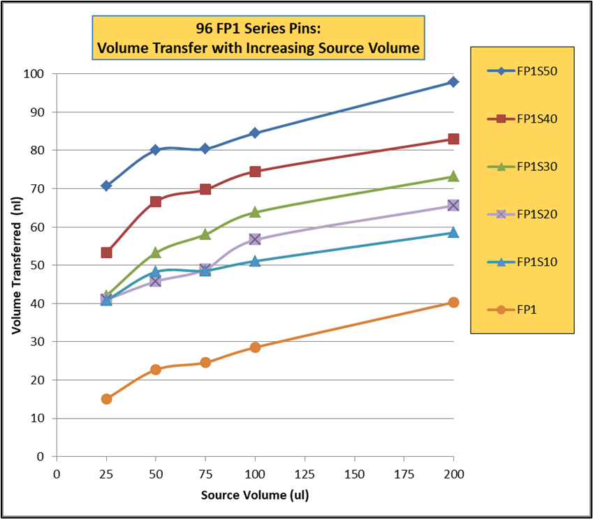
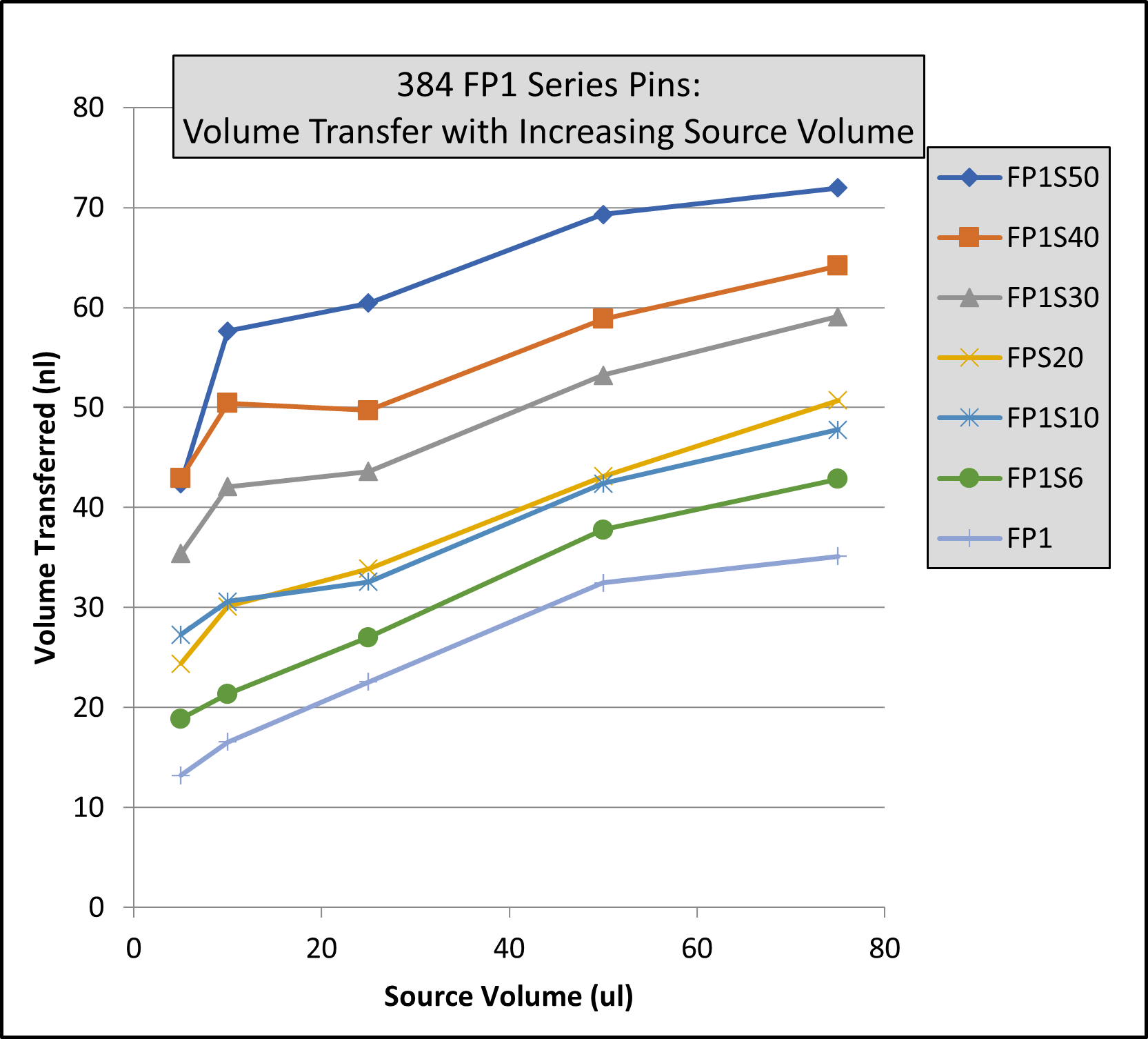
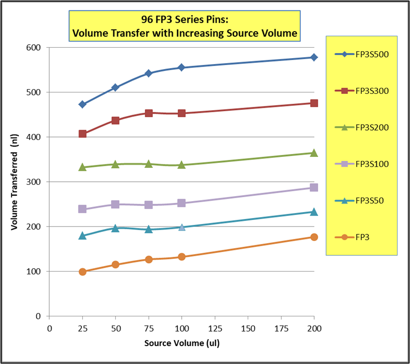
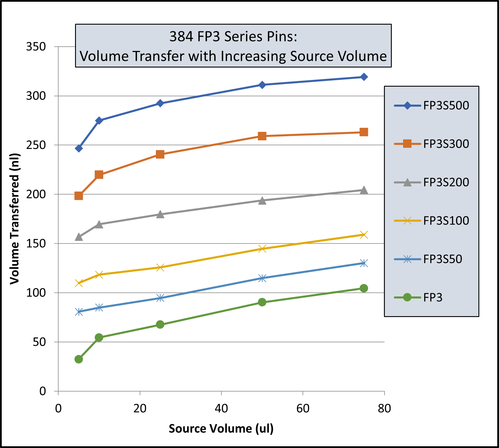
Pin Type | Pin Diameter(mm) | Shape | 96 Format Low Range(nL)² | 96 Format High Range(nL)² | 384 Format Low Range(nL)³ | 384 Format High Range(nL)³ |
---|---|---|---|---|---|---|
FP9 | 0.229 | Solid | 4 | 10 | 3 | 8 |
FP8 | 0.35 | Solid | 13 | 26 | 6 | 18 |
FP1 | 0.457 | Solid | 18 | 43 | 11 | 31 |
FP1S6 | 0.457 | 6nL Slot | 24 | 49 | 15 | 34 |
FP1S10 | 0.457 | 10nL Slot | 30 | 54 | 21 | 40 |
FP1S20 | 0.457 | 20nL Slot | 37 | 61 | 27 | 46 |
FP1S30 | 0.457 | 30nL Slot | 46 | 68 | 35 | 54 |
FP1S40 | 0.457 | 40nL Slot | 57 | 78 | 45 | 63 |
FP1S50 | 0.457 | 50nL Slot | 70 | 90 | 56 | 75 |
FP3 | 0.787 | Solid | 67 | 139 | 29 | 79 |
FP4 | 0.91 | Solid | 94 | 197 | 34 | 98 |
FP3S100 | 0.787 | 100nL Slot | 175 | 241 | 114 | 163 |
FP3S200 | 0.787 | 200nL Slot | 280 | 332 | 203 | 250 |
FP3S500 | 0.787 | 500nL Slot | 535 | 559 | 427 | 464 |
FP4S1000 | 0.91 | 1000nL Slot | 940 | 1011 | 704 | 800 |
FP4S2000 | 0.91 | 2000nL Slot | 1518 | 1608 | 1277 | 1362 |
Footnotes: (1) Delivery volume range is determined by speed of withdrawal from source liquid: Z-Speed Range = 1.5-30 mm/sec, slow speed = low volume delivery range, fast speed = high volume delivery range (2) 200ul source plate volume per well (3) 75ul source plate volume per well |
Pin Type | Pin Diameter (mm) | Shape | 96 Format Low Range(nL)² | 96 Format High Range(nL)² | 384 Format Low Range(nL)³ | 384 Format High Range(nL)³ |
---|---|---|---|---|---|---|
FP9H | 0.229 | Solid | 4 | 10 | 3 | 8 |
FP8H | 0.35 | Solid | 9 | 24 | 6 | 17 |
FP1H | 0.457 | Solid | 15 | 39 | 9 | 27 |
FP1S6H | 0.457 | 6nL Slot | 23 | 49 | 14 | 32 |
FP1S10H | 0.457 | 10nL Slot | 29 | 53 | 20 | 38 |
FP1S20H | 0.457 | 20nL Slot | 35 | 59 | 26 | 43 |
FP1S30H | 0.457 | 30nL Slot | 47 | 69 | 35 | 53 |
FP1S40H | 0.457 | 40nL Slot | 54 | 75 | 41 | 58 |
FP1S50H | 0.457 | 50nL Slot | 69 | 90 | 57 | 73 |
FP3H | 0.787 | Solid | 67 | 134 | 27 | 76 |
FP4H | 0.91 | Solid | 95 | 189 | 32 | 102 |
FP3S100H | 0.787 | 100nL Slot | 170 | 227 | 108 | 164 |
FP3S200H | 0.787 | 200nL Slot | 266 | 320 | 190 | 239 |
FP3S500H | 0.787 | 500nL Slot | 520 | 542 | 416 | 456 |
FP4S1000H | 0.91 | 1000nL Slot | 932 | 1000 | 741 | 805 |
FP4S2000H | 0.91 | 2000nL Slot | 1571 | 1638 | 1351 | 1423 |
Footnotes: (1) Delivery volume range is determined by speed of withdrawal from source liquid: Z-Speed Range = 1.5-30 mm/sec, slow speed = low volume delivery range, fast speed = high volume delivery range (2) 200ul source plate volume per well (3) 75ul source plate volume per well |
Pin Type | Diameter (mm) | Shape | 96 Format Low Range(nL)² | 96 Format High Range(nL)² | 384 Format Low Range(nL)³ | 384 Format High Range(nL)³ |
---|---|---|---|---|---|---|
FP | 1.58 | Solid Pointed | 147 | 411 | 168 | 395 |
FPS.5 | 1.58 | 500nL Slot | 442 | 704 | 631 | 843 |
FPS | 1.58 | 1000nL Slot | 893 | 1130 | 1343 | 1498 |
FPS2 | 1.58 | 2000nL Slot | 1911 | 2038 | 2607 | 2767 |
FPS5 | 1.58 | 5000nL Slot | 3908 | 4296 | 5180 | 5253 |
FP6 | 1.58 | Solid Flat | 323 | 674 | 154 | 398 |
FP6S.5 | 1.58 | 500nL Slot | 734 | 1042 | 855 | 1053 |
FP6S | 1.58 | 1000nL Slot | 1210 | 1500 | 1638 | 1717 |
FP6S2 | 1.58 | 2000nL Slot | 2299 | 2384 | 2787 | 3068 |
FP6S5 | 1.58 | 5000nL Slot | 4329 | 4656 | 5237 | 5245 |
Footnotes:(1) Delivery volume range is determined by speed of withdrawal from source liquid: Z-Speed Range = 1.5-30 mm/sec, slow speed = low volume delivery range, fast speed = high volume delivery range (2) 200ul source plate volume per well (3) 75ul source plate volume per well |