")
")
")
")
")
")
")
")
")
")
 Powered by Bioz
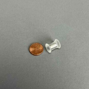
STIR ELEMENT, DUMBBELL, Four Encapsulated NdFeB Magnets, 52 MGO, High-Temperature Resin, 20mm Diameter, 59mm Length, 80°C Max Operating Temp for Magnets
STIR ELEMENT, DUMBBELL, Four Encapsulated NdFeB Magnets, 52 MGO, High-Temperature Resin, 20mm Diameter, Used in Bottles
STIR ELEMENT, DUMBBELL, Four Encapsulated NdFeB Magnets, 52 MGO, High-Temperature Resin, 20mm Diameter, 59mm Length, 80°C Max Operating Temp for Magnets
| Shape | Dumbbell |
|---|---|
| Container Used | Bottles |
| Bottle Volume | 500mL |
| Diameter | 20mm |
| Length | 59mm |
| Magnet Type | Neodymium (NdFeB) |
| Magnet Strength | 52MGO |
| Temp Resistant | 80°C Max Operating Temp |
| Autoclavable | Yes |
| Encapsulation/Coating | High-Temp Resin |
| No of Magnets | 4 |
| Magnet Dimensions | 6mm x 10mm |
| Sterilizable by Gamma Radiation | No |
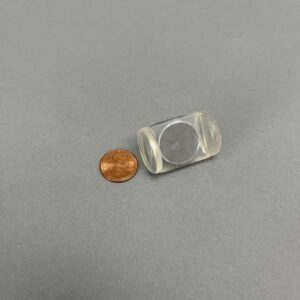
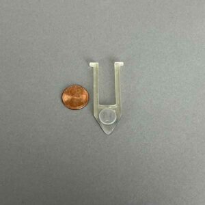
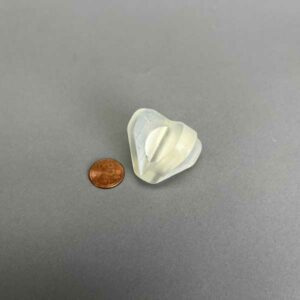
The ability to make and use NdFeB stir elements to stir very viscous solutions and tightly couple them for high-speed mixing procedures has long been the goal of scientists. Also, the ability to use the flexibility of 3D printing to easily make Stir Elements of any shape is a significant advantage over the molding process typically used to encapsulate magnetic stirrers. The cost of making a mold is significantly high and the temperatures necessary to make the encapsulating material (like PTFE) molten is high enough to destroy the magnetic ability of NdFeB. The ability to 3D print and encapsulate NdFeB means that prototypes of a unique design can be made in a single day for less than $50.00, and if successful, the process can be automated for production runs of hundreds of parts per day.
In addition to the rare earth magnets NdFeB and SmCo, lesser expensive AlNiCo or Magnetic Stainless Steel can also be encapsulated by this method.
Most Stir elements on the market today employ PTFE encapsulation via a molding process of AlNiCo or SmCo magnets. No company has been able to PTFE encapsulate NdFeB because the temperature necessary for melting the PTFE destroys the magnetic character of the NdFeB. NdFeB magnets are the strongest of all magnetic materials and therefore the most useful in mixing viscous liquids. Also, the strength of NdFeB stir elements is useful in high-speed stirring applications because they remain strongly coupled to the drive magnet. We were the first to produce PVDF and PEEK encapsulation of NdFeB stir elements. We developed a system of molding simple hollow cores from PVDF and PEEK and then placing a NdFeB magnetic cylinder into the hollow core and sonically welding the two cores together. This method works with simple cylinder designs but not with complex designs because of the limits of sonic welders.
We have also developed a vapor deposition process using Parylene to encapsulate NdFeB magnets that protects them from caustic solutions but the soft parylene coating is quickly worn off by the friction of stirring against a glass or plastic surface. We sought to protect the Parylene coating by taking a sheet of PTFE and using an end mill to make identical pockets on both side of the PTFE sheet leaving a 2 mm thick membrane of PTFE between the two pockets and placing a Parylene coated NdFeB disc into each of the pockets, so they are held in the pocket magnetically. This method protects the Parylene coating and allows for more complex stirrer designs, however cleaning these stir elements requires taking the parylene-coated NdFeB magnets out and cleaning the pockets and the parylene-coated magnets after each use to prevent cross-contamination. A cumbersome and time-consuming process.
We start by making a stereolithography 3D printed stir element that has one or more slot openings in the top surface that will accommodate one or more magnets. Once the support structure is removed, the magnet(s) are placed into the slot or slots and a liquid form of the same high-temperature and chemically resistant resin is poured into the slot covering the magnet. The stir element is then placed into a UV light chamber to cure (harden) the resin and encapsulate the magnet. The Stir element is further hardened by placing in an oven at 80° C for 120 minutes. 3D stereolithography printing allows for many custom and complex designs, while still fully encapsulating the magnet. The ability to capture the utility of stereolithography 3D printing makes this method an inexpensive prototyping masterpiece. The resin formulation allows for traditional sterilizing methods, such as autoclaving and gamma radiation, to be used.
The High Temp 3D resin has been Solvent tested by the source of the resin and by V&P Scientific, Inc. and holds up very well against most common solvents except Chloroform and strong acids. See the tables below and the testing protocols.
HIGH-TEMPERATURE RESIN SOLVENT COMPATIBILITY TABLE
V&P Scientific, Inc. Testing
The following table represents the difference between the initial measurements and weight compared to those after a 24-hour exposure to the solvents.
| CHEMICAL | X(mm) | Y(mm) | Z(mm) | vol (mm3) | weight(g) | vol(%) | weight(%) | pH |
|---|---|---|---|---|---|---|---|---|
| Acetonitrile | 0.05 | 0.01 | 0.03 | 9.28 | 0.00 | 0.88 | 0.00 | 10.00 |
| Chloroform | 0.03 | 0.08 | 0.13 | 24.75 | 0.03 | 2.36 | 2.38 | 4.5 |
| Dimethyl Sulfoxide | 0.00 | 0.03 | 0.00 | 3.10 | 0.00 | 0.30 | 0.00 | 9.00 |
| Dimethylformamide | 0.02 | 0.01 | 0.02 | 5.16 | 0.01 | 0.49 | 0.81 | 6.70 |
| Ethyl Acetate | 0.01 | 0.02 | 0.03 | 6.27 | 0.01 | 0.59 | 0.81 | 6.50 |
| Trifluoroacetic Acid | 0.02 | (0.28) | 0.03 | (23.14) | (0.03) | (2.20) | (2.42) | 1.00 |
Resin Supplier Testing
Percentage weight gain over 24 hours for a printed and post-cured 10mm x 10mm x 10mm cube immersed in the respective solvent.
| CHEMICAL | vol(%) gain | weight(%) gain |
|---|---|---|
| Acetic Acid, 5% | <1 | <1 |
| Acetone | <1 | <1 |
| Isopropyl Alcohol | <1 | <1 |
| Bleach 5% | <1 | <1 |
| Butyl Acetate | <1 | <1 |
| Diesel Fuel | <1 | <1 |
| Diethyl Glycol Monomethyl Ether | <1 | <1 |
| Hydraulic Oil | <1 | <1 |
| Skydrol 5 | <1 | <1 |
| Hydrogen Peroxide (3%) | <1 | <1 |
| Isooctante (Gasoline) | <1 | <1 |
| Mineral Oil (Light) | <1 | <1 |
| Mineral Oil (Heavy) | <1 | <1 |
| Salt Water (3.5%) Nacl | <1 | <1 |
| Sodium Hydroxide | <1 | <1 |
| Water | <1 | <1 |
| Xyline | <1 | <1 |
| Hydrochloric Acid | 1.2 | <1 |
| Pin | Description | nl Transferred | CV% | |
|---|---|---|---|---|
| 0.229 mm diameter (FP9) | Total Pin | Uncoated | 7.41 | 2.4 |
| Hydrophobic | 7.46 | 5.4 | ||
| 0.229 mm diameter (FP9) | Hanging Drop | Uncoated | N/A | N/A |
| Hydrophobic | 2.09 | 3.8 | ||
| 0.457 mm diameter (FP1) | Total Pin | Uncoated | 33.48 | 3.2 |
| Hydrophobic | 28.17 | 7.5 | ||
| 0.457 mm diameter (FP1) | Hanging Drop | Uncoated | 16.96 | 4.5 |
| Hydrophobic | 8.51 | 0.8 | ||
| 0.787 mm diameter (FP3) | Total Pin | Uncoated | 87.32 | 3.9 |
| Hydrophobic | 77.4 | 3.9 | ||
| 0.787 mm diameter (FP3) | Hanging Drop | Uncoated | 48.77 | 1.2 |
| Hydrophobic | 43.05 | 9.4 | ||
| 1.19 mm diameter (VP 409 & VP 386) | Total Pin | Uncoated | 247.22 | 2.8 |
| Hydrophobic | 192.67 | 2.6 | ||
| 1.19 mm diameter (VP 409 & VP 386) | Hanging Drop | Uncoated | 76.35 | 1.6 |
| Hydrophobic | 108.4 | 2.8 | ||
| 1.58 mm diameter (VP 408 & VP 384) | Total Pin | Uncoated | 273.5 | 4.6 |
| Hydrophobic | 259.25 | 3.1 | ||
| 1.58 mm diameter (VP 408 & VP 384) | Hanging Drop | Uncoated | 201.93 | 5 |
| Hydrophobic | 170.04 | 7.5 |
Transfer Of Horseradish Peroxidase In Tris Buffered Saline With Pin Tools
Coating pins will reduce the total amount of liquid transferred and also reduce the amount of non-specific binding to the stainless-steel pins. If the substance you are transferring has high non-specific binding this will be an important factor in selecting your pins.
| Pin | Description | nl Transferred | CV% | |
|---|---|---|---|---|
| 0.229 mm diameter (FP9) | Total Pin | Uncoated | 7.41 | 2.4 |
| Hydrophobic | 7.46 | 5.4 | ||
| 0.229 mm diameter (FP9) | Hanging Drop | Uncoated | N/A | N/A |
| Hydrophobic | 2.09 | 3.8 | ||
| 0.457 mm diameter (FP1) | Total Pin | Uncoated | 33.48 | 3.2 |
| Hydrophobic | 28.17 | 7.5 | ||
| 0.457 mm diameter (FP1) | Hanging Drop | Uncoated | 16.96 | 4.5 |
| Hydrophobic | 8.51 | 0.8 | ||
| 0.787 mm diameter (FP3) | Total Pin | Uncoated | 87.32 | 3.9 |
| Hydrophobic | 77.4 | 3.9 | ||
| 0.787 mm diameter (FP3) | Hanging Drop | Uncoated | 48.77 | 1.2 |
| Hydrophobic | 43.05 | 9.4 | ||
| 1.19 mm diameter (VP 409 & VP 386) | Total Pin | Uncoated | 247.22 | 2.8 |
| Hydrophobic | 192.67 | 2.6 | ||
| 1.19 mm diameter (VP 409 & VP 386) | Hanging Drop | Uncoated | 76.35 | 1.6 |
| Hydrophobic | 108.4 | 2.8 | ||
| 1.58 mm diameter (VP 408 & VP 384) | Total Pin | Uncoated | 273.5 | 4.6 |
| Hydrophobic | 259.25 | 3.1 | ||
| 1.58 mm diameter (VP 408 & VP 384) | Hanging Drop | Uncoated | 201.93 | 5 |
| Hydrophobic | 170.04 | 7.5 |
Transfer Of Horseradish Peroxidase In Tris Buffered Saline With Pin Tools
Although the slots in the pin are a precise volume, the liquid that is transferred is usually more. The reason for this is due to the surface tension of the liquid causing the liquid in the slot to “bow out” thus increasing the volume of the liquid in the slot. If is important for you to transfer exactly a certain volume we can make custom slots to match the surface tension characteristics of your liquid
| Solvent/Sample | Concentration | CV% | nl FITC Transferred | CV% | nl FITC Transferred |
|---|---|---|---|---|---|
| Uncoated | Uncoated | Hydrophobic Coated | Hydrophobic Coated | ||
| DMSO (-) | 0 | 8.1 | 353.42 | 7.5 | 298.72 |
| DMSO + DNA (mg/ml) | 0.5 | 6.6 | 497.21 | 6.6 | 435.86 |
| 0.25 | 9 | 432.49 | 4.1 | 391.93 | |
| 0.125 | 8.9 | 363.64 | 0.9 | 344.75 | |
| 0.0625 | 2.3 | 381.86 | 2 | 331.68 | |
| 0.0313 | 1.5 | 378.03 | 4.4 | 331.71 | |
| 0.0156 | 1.2 | 357.52 | 1.4 | 329.03 | |
| Tris (-) | 0 | 4.9 | 577.31 | 7.2 | 493.53 |
| Tris + DNA (mg/ml) | 0.5 | 4.5 | 540.53 | 1.1 | 477.5 |
| 0.25 | 4.6 | 518.21 | 6.1 | 456.75 | |
| 0.125 | 15.8 | 583.25 | 4.1 | 438.82 | |
| 0.0625 | 4.2 | 551.17 | 3.1 | 433.69 | |
| 0.0313 | 4.4 | 536.66 | 2.3 | 458.37 | |
| 0.0156 | 2.9 | 528.53 | 1.2 | 441.1 | |
| Tris + BSA (%) | 4 | 5.4 | 462.13 | 11 | 409.27 |
| 1 | 4 | 452.86 | 2.7 | 426.58 | |
| 0.25 | 11.7 | 456.45 | 1.3 | 408.72 | |
| 0.0625 | 1.1 | 445.22 | 6.5 | 393.07 | |
| 0.0156 | 3.7 | 462.85 | 3.9 | 430.2 | |
| 0.0039 | 1.5 | 493.54 | 2.2 | 437.29 | |
| 0.001 | 2.9 | 504.25 | 0.7 | 475.96 |
1. Increasing the concentration of DNA (sheared salmon sperm) to .25 mg/ml significantly increases the volume of DMSO liquid transferred for both coated and uncoated FP3S500 Slot Pins.
2. Increasing the concentration of DNA does not significantly increase the volume of Tris buffer (aqueous) transferred by both coated and uncoated FP3S500 Slot Pins.
3. Increasing the concentration of BSA (Bovine Serum Albumin) significantly decreases the volume of Tris buffer transferred by both coated and uncoated FP3S500 Slot Pins.
4. Hydrophobic coated FP3S500 Slot Pins transferred less DMSO – DNA and less Tris DNA and less Tris BSA than the uncoated FP3S500 Slot Pins.
5. Both coated and uncoated FP3S500 pins transfer significantly more aqueous solution than DMSO.
| Solvent/Sample | Concentration | CV% | nl FITC Transferred | CV% | nl FITC Transferred |
|---|---|---|---|---|---|
| Uncoated | Uncoated | Hydrophobic Coated | Hydrophobic Coated | ||
| DMSO (-) | 0 | 4.2 | 49.38 | 2.1 | 49.31 |
| DMSO + DNA (mg/ml) | 0.5 | 4.9 | 51.24 | 2.6 | 56.79 |
| 0.25 | 1.7 | 50.2 | 1.2 | 49.53 | |
| 0.125 | 1.5 | 51.27 | 2.3 | 49.77 | |
| 0.0625 | 2.2 | 49.34 | 4.1 | 48.19 | |
| 0.0313 | 1.2 | 49.03 | 0.2 | 50.23 | |
| 0.0156 | 2.4 | 45.9 | 1.4 | 46.64 | |
| Tris (-) | 0 | 2.6 | 89.51 | 2.9 | 91.34 |
| Tris + DNA (mg/ml) | 0.5 | 7 | 77.11 | 0.6 | 84.62 |
| 0.25 | 3.9 | 82.22 | 1.6 | 84.89 | |
| 0.125 | 3.9 | 85.42 | 1 | 85.08 | |
| 0.0625 | 1.5 | 85.36 | 2.8 | 85.03 | |
| 0.0313 | 2 | 84.52 | 3 | 88.19 | |
| 0.0156 | 2.6 | 82.92 | 2.8 | 83.2 |
1. In contrast to the FP3S500 data, increasing the concentration of DNA to .25 mg/ml does not significantly increase the volume of DMSO liquid transferred for both coated and uncoated FP1S50 Slot Pins.
2. Increasing the concentration of DNA does not significantly increase the volume of Tris buffer (aqueous) transferred by both coated and uncoated FP1S50 Slot Pins.
3. In contrast to the FP3S500 data, FP1S50 coated pins transferred about the same volume of DNA at all concentrations as did uncoated pins.
4. Both coated and uncoated FP1S50 pins transfer significantly more aqueous solution than DMSO.
5. The differences between the FP3S500 and the FP1S50 pin may be due to the different pin diameter’s effect on contact angle and therefore on the “wetting” of the pin. See the diagram on the link to / ah energy system.
| Pin | Description | nl Transferred | CV% | |
|---|---|---|---|---|
| 0.229 mm diameter (FP9) | Total Pin | Uncoated | 7.41 | 2.4 |
| Hydrophobic | 7.46 | 5.4 | ||
| 0.229 mm diameter (FP9) | Hanging Drop | Uncoated | N/A | N/A |
| Hydrophobic | 2.09 | 3.8 | ||
| 0.457 mm diameter (FP1) | Total Pin | Uncoated | 33.48 | 3.2 |
| Hydrophobic | 28.17 | 7.5 | ||
| 0.457 mm diameter (FP1) | Hanging Drop | Uncoated | 16.96 | 4.5 |
| Hydrophobic | 8.51 | 0.8 | ||
| 0.787 mm diameter (FP3) | Total Pin | Uncoated | 87.32 | 3.9 |
| Hydrophobic | 77.4 | 3.9 | ||
| 0.787 mm diameter (FP3) | Hanging Drop | Uncoated | 48.77 | 1.2 |
| Hydrophobic | 43.05 | 9.4 | ||
| 1.19 mm diameter (VP 409 & VP 386) | Total Pin | Uncoated | 247.22 | 2.8 |
| Hydrophobic | 192.67 | 2.6 | ||
| 1.19 mm diameter (VP 409 & VP 386) | Hanging Drop | Uncoated | 76.35 | 1.6 |
| Hydrophobic | 108.4 | 2.8 | ||
| 1.58 mm diameter (VP 408 & VP 384) | Total Pin | Uncoated | 273.5 | 4.6 |
| Hydrophobic | 259.25 | 3.1 | ||
| 1.58 mm diameter (VP 408 & VP 384) | Hanging Drop | Uncoated | 201.93 | 5 |
| Hydrophobic | 170.04 | 7.5 |
Hydrophobic coating pins will reduce the total amount of aqueous HRP liquid transferred and also reduce the amount of non-specific binding to the stainless-steel pins. If the substance you are transferring has high non-specific binding this will be an important factor in selecting your pins.
Pin diameter also has an effect on the degree of reduction of liquid transfer with hydrophobic coating as the smaller the diameter the less the reduction of transfer. This is most likely due to the curvature of the pin affecting the wetting contact angle
| Pin | Description | nl Transferred | CV% | ||
|---|---|---|---|---|---|
| 0.457 mm diameter (FP1) | 6 nl Slot | Total Pin* | Uncoated | 25.6 | 10.8 |
| Hydrophobic | N/A | N/A | |||
| 10 nl Slot | Total Pin* | Uncoated | 23.36 | 6.1 | |
| Hydrophobic | 25.85 | 6.9 | |||
| 50 nl Slot | Total Pin* | Uncoated | 67.83 | 2.5 | |
| Hydrophobic | N/A | N/A | |||
| 0.787 mm diameter (FP3) | 100 nl Slot | Total Pin* | Uncoated | 180.32 | 7.2 |
| Hydrophobic | 205.84 | 5.5 | |||
| 200 nl Slot | Total Pin* | Uncoated | 277.82 | 4.9 | |
| Hydrophobic | 287.3 | 3.8 | |||
| 500 nl Slot | Total Pin* | Uncoated | 581.16 | 5.2 | |
| Hydrophobic | 555.69 | 3 |
Hydrophobic coating pins will slightly increase the total amount of DMSO FITC liquid transferred.
| Pin | Description | nl Transferred | CV% | |
|---|---|---|---|---|
| 0.787 mm diameter (FP3) | 100 nl Slot Total Pin, Including Slot | Uncoated | 195.69 | 1.6 |
| Hydrophobic | 170.2 | 2.9 | ||
| 0.787 mm diameter (FP3) | 100 nl Slot, Slot Only | Uncoated | 149.67 | 4.9 |
| Hydrophobic | 129.61 | 7.6 | ||
| 0.787 mm diameter (FP3) | 200 nl Slot Total Pin, Including Slot | Uncoated | 269.77 | 1.9 |
| Hydrophobic | 228.62 | 17.1 | ||
| 0.787 mm diameter (FP3) | 200 nl Slot, Slot Only | Uncoated | 237.52 | 8.9 |
| Hydrophobic | 186.9 | 5.9 |
Although the slots in the pin are a precise volume, the liquid that is transferred is usually more because of the volume carried on the sides of the pins.
As seen with other aqueous data the amount transferred on hydrophobic coated Slot pins is less than on uncoated Solid or Slot pins. Thus Hydrophobic coating has the most effect on aqueous transfers.

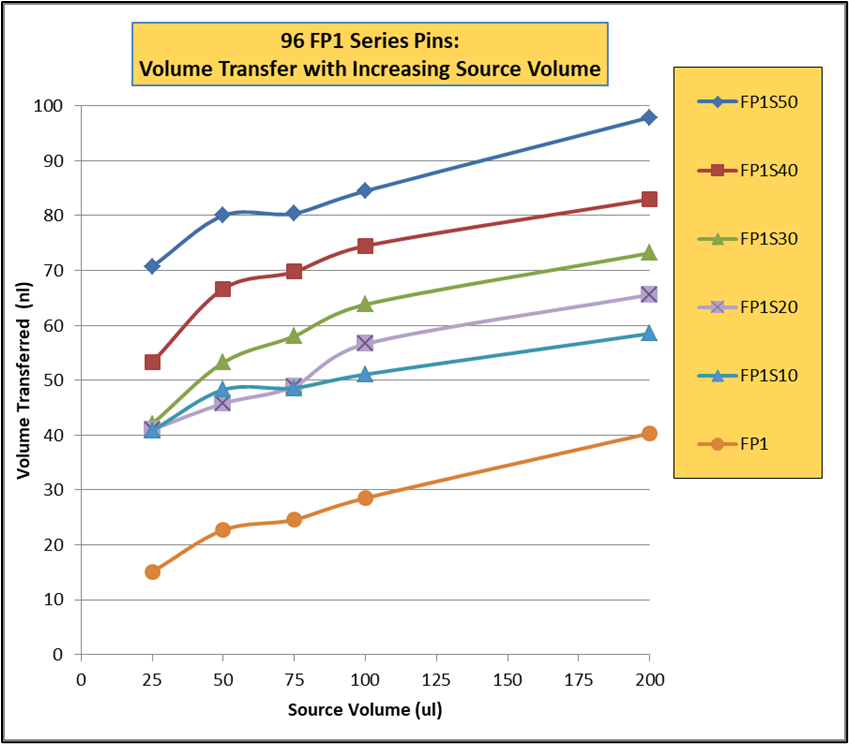
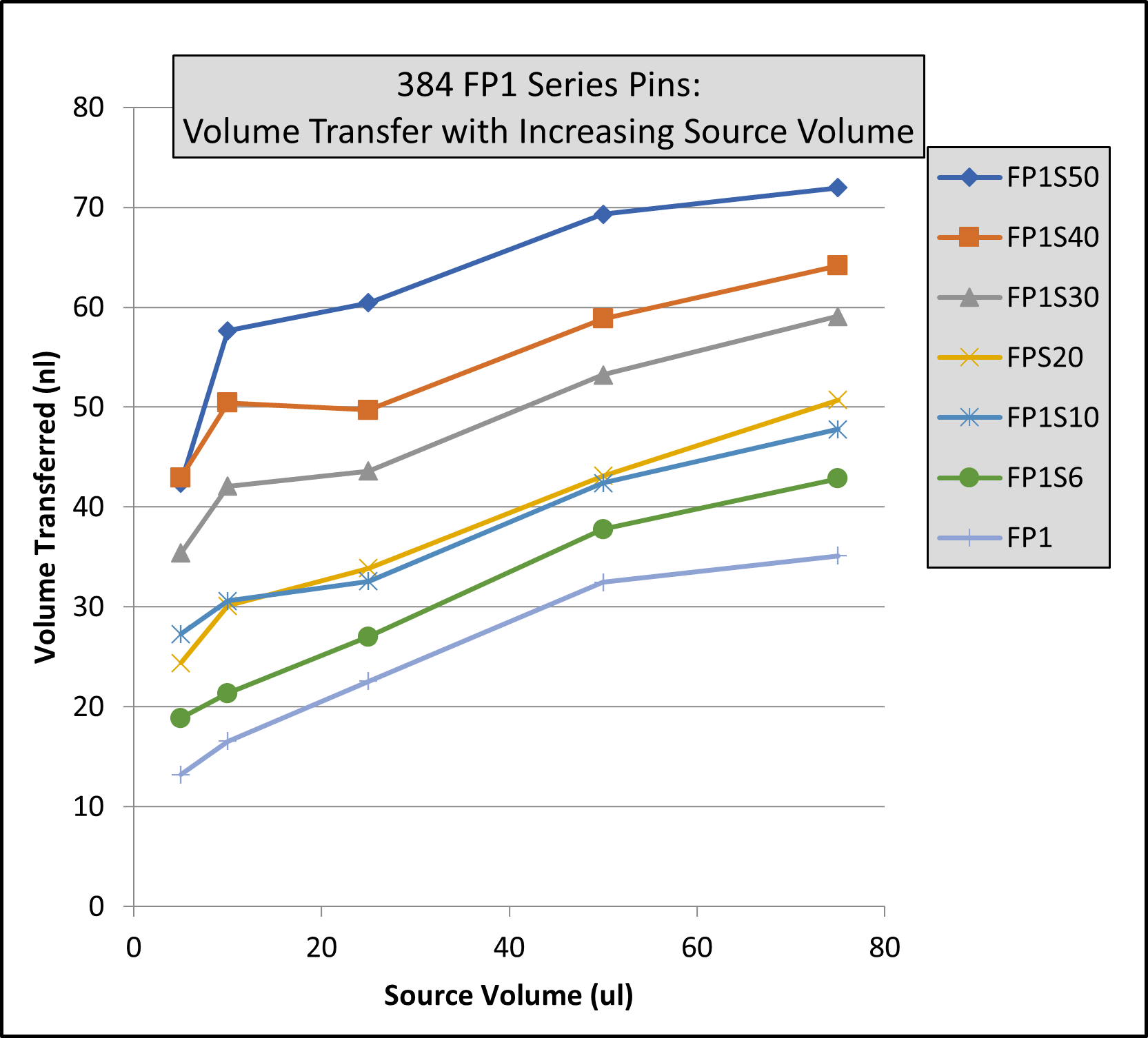
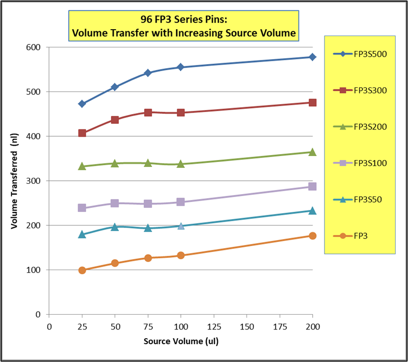
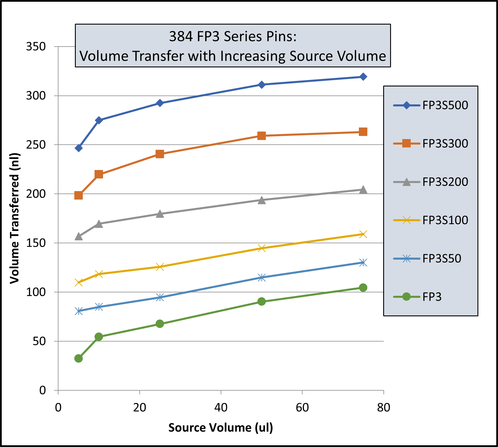
Note: Same volume (200ul for 96 Format and 74 ul for 384 Format) in recipient plates and same pin withdrawal speed for all pins. Changes to pin withdrawal speed or volume in the source plate can result in different volumes being transferred.
Transfer volumes should always be confirmed by customers for their assay conditions and automated system.
| Pin Type | Pin Diameter(mm) | Shape | 96 Format Low Range(nL)² | 96 Format High Range(nL)² |
|---|---|---|---|---|
| FP9 | 0.229 | Solid | 13 | 39 |
| FP8 | 0.356 | Solid | 15 | 37 |
| FP1 | 0.457 | Solid | 22 | 61 |
| FP1S6 | 0.457 | 6nL Slot | 34 | 67 |
| FP1S10 | 0.457 | 10nL Slot | 39 | 74 |
| FP1S50 | 0.457 | 50nL Slot | 90 | 124 |
| FP3 | 0.787 | Solid | 93 | 213 |
| FP3S100 | 0.787 | 100nL Slot | 213 | 334 |
| FP3S200 | 0.787 | 200nL Slot | 311 | 449 |
| FP3S500 | 0.787 | 500nL Slot | 515 | 671 |
| FP4 | 0.914 | Solid | 126 | 289 |
| Footnotes: (1) Delivery volume range is determined by speed of withdrawal from source liquid: Z-Speed Range = 1.5-30 mm/sec, slow speed = low volume delivery range, fast speed = high volume delivery range (2) 200ul source plate volume per well | ||||
| Pin Type | Pin Diameter(mm) | Shape | 96 Format Low Range(nL)² | 96 Format High Range(nL)² |
|---|---|---|---|---|
| FP9 | 0.229 | Solid | 13 | 38 |
| FP8 | 0.356 | Solid | ||
| FP1 | 0.457 | Solid | 23 | 60 |
| FP1S6 | 0.457 | 6nL Slot | 33 | 67 |
| FP1S10 | 0.457 | 10nL Slot | 40 | 75 |
| FP1S50 | 0.457 | 50nL Slot | 86 | 119 |
| FP3 | 0.787 | Solid | 76 | 209 |
| FP3S100 | 0.787 | 100nL Slot | 188 | 324 |
| FP3S200 | 0.787 | 200nL Slot | 288 | 436 |
| FP3S500 | 0.787 | 500nL Slot | 473 | 649 |
| FP4 | 0.914 | Solid | ||
| Footnotes: (1) Delivery volume range is determined by speed of withdrawal from source liquid: Z-Speed Range = 1.5-30 mm/sec, slow speed = low volume delivery range, fast speed = high volume delivery range (2) 200ul source plate volume per well | ||||
| Pin Type | Pin Diameter(mm) | Shape | Low Range(nL)² | High Range(nL)² |
|---|---|---|---|---|
| FP | 1.58 | Solid Pointed | 175 | 594 |
| FPS.5 | 1.58 | 500nL Slot | 524 | 962 |
| FPS | 1.58 | 1000nL Slot | 1056 | 1476 |
| FPS2 | 1.58 | 2000nL Slot | 1739 | 2174 |
| FPS5 | 1.58 | 5000nL Slot | 5150 | 4953 |
| FP6 | 1.58 | Solid Flat | 465 | 960 |
| FP6S.5 | 1.58 | 500nL Slot | 934 | 1445 |
| FP6S | 1.58 | 1000nL Slot | 1396 | 1930 |
| FP6S2 | 1.58 | 2000nL Slot | 2072 | 2637 |
| FP6S5 | 1.58 | 5000nL Slot | 4820 | 4693 |
| Footnotes:(1) Delivery volume range is determined by speed of withdrawal from source liquid: Z-Speed Range = 1.5-30 mm/sec, slow speed = low volume delivery range, fast speed = high volume delivery range (2) 200ul source plate volume per well for 96 Format and 75ul source plate volume per well for 384 Format |
||||
| Pin Type | Pin Diameter(mm) | Shape | 96 Format Low Range(nL)² | 96 Format High Range(nL)² | 384 Format Low Range(nL)³ | 384 Format High Range(nL)³ |
|---|---|---|---|---|---|---|
| FP9 | 0.229 | Solid | 4 | 10 | 3 | 8 |
| FP8 | 0.35 | Solid | 13 | 26 | 6 | 18 |
| FP1 | 0.457 | Solid | 18 | 43 | 11 | 31 |
| FP1S6 | 0.457 | 6nL Slot | 24 | 49 | 15 | 34 |
| FP1S10 | 0.457 | 10nL Slot | 30 | 54 | 21 | 40 |
| FP1S20 | 0.457 | 20nL Slot | 37 | 61 | 27 | 46 |
| FP1S30 | 0.457 | 30nL Slot | 46 | 68 | 35 | 54 |
| FP1S40 | 0.457 | 40nL Slot | 57 | 78 | 45 | 63 |
| FP1S50 | 0.457 | 50nL Slot | 70 | 90 | 56 | 75 |
| FP3 | 0.787 | Solid | 67 | 139 | 29 | 79 |
| FP4 | 0.91 | Solid | 94 | 197 | 34 | 98 |
| FP3S100 | 0.787 | 100nL Slot | 175 | 241 | 114 | 163 |
| FP3S200 | 0.787 | 200nL Slot | 280 | 332 | 203 | 250 |
| FP3S500 | 0.787 | 500nL Slot | 535 | 559 | 427 | 464 |
| FP4S1000 | 0.91 | 1000nL Slot | 940 | 1011 | 704 | 800 |
| FP4S2000 | 0.91 | 2000nL Slot | 1518 | 1608 | 1277 | 1362 |
| Footnotes: (1) Delivery volume range is determined by speed of withdrawal from source liquid: Z-Speed Range = 1.5-30 mm/sec, slow speed = low volume delivery range, fast speed = high volume delivery range (2) 200ul source plate volume per well (3) 75ul source plate volume per well | ||||||
| Pin Type | Pin Diameter (mm) | Shape | 96 Format Low Range(nL)² | 96 Format High Range(nL)² | 384 Format Low Range(nL)³ | 384 Format High Range(nL)³ |
|---|---|---|---|---|---|---|
| FP9H | 0.229 | Solid | 4 | 10 | 3 | 8 |
| FP8H | 0.35 | Solid | 9 | 24 | 6 | 17 |
| FP1H | 0.457 | Solid | 15 | 39 | 9 | 27 |
| FP1S6H | 0.457 | 6nL Slot | 23 | 49 | 14 | 32 |
| FP1S10H | 0.457 | 10nL Slot | 29 | 53 | 20 | 38 |
| FP1S20H | 0.457 | 20nL Slot | 35 | 59 | 26 | 43 |
| FP1S30H | 0.457 | 30nL Slot | 47 | 69 | 35 | 53 |
| FP1S40H | 0.457 | 40nL Slot | 54 | 75 | 41 | 58 |
| FP1S50H | 0.457 | 50nL Slot | 69 | 90 | 57 | 73 |
| FP3H | 0.787 | Solid | 67 | 134 | 27 | 76 |
| FP4H | 0.91 | Solid | 95 | 189 | 32 | 102 |
| FP3S100H | 0.787 | 100nL Slot | 170 | 227 | 108 | 164 |
| FP3S200H | 0.787 | 200nL Slot | 266 | 320 | 190 | 239 |
| FP3S500H | 0.787 | 500nL Slot | 520 | 542 | 416 | 456 |
| FP4S1000H | 0.91 | 1000nL Slot | 932 | 1000 | 741 | 805 |
| FP4S2000H | 0.91 | 2000nL Slot | 1571 | 1638 | 1351 | 1423 |
| Footnotes: (1) Delivery volume range is determined by speed of withdrawal from source liquid: Z-Speed Range = 1.5-30 mm/sec, slow speed = low volume delivery range, fast speed = high volume delivery range (2) 200ul source plate volume per well (3) 75ul source plate volume per well | ||||||
| Pin Type | Diameter (mm) | Shape | 96 Format Low Range(nL)² | 96 Format High Range(nL)² | 384 Format Low Range(nL)³ | 384 Format High Range(nL)³ |
|---|---|---|---|---|---|---|
| FP | 1.58 | Solid Pointed | 147 | 411 | 168 | 395 |
| FPS.5 | 1.58 | 500nL Slot | 442 | 704 | 631 | 843 |
| FPS | 1.58 | 1000nL Slot | 893 | 1130 | 1343 | 1498 |
| FPS2 | 1.58 | 2000nL Slot | 1911 | 2038 | 2607 | 2767 |
| FPS5 | 1.58 | 5000nL Slot | 3908 | 4296 | 5180 | 5253 |
| FP6 | 1.58 | Solid Flat | 323 | 674 | 154 | 398 |
| FP6S.5 | 1.58 | 500nL Slot | 734 | 1042 | 855 | 1053 |
| FP6S | 1.58 | 1000nL Slot | 1210 | 1500 | 1638 | 1717 |
| FP6S2 | 1.58 | 2000nL Slot | 2299 | 2384 | 2787 | 3068 |
| FP6S5 | 1.58 | 5000nL Slot | 4329 | 4656 | 5237 | 5245 |
| Footnotes:(1) Delivery volume range is determined by speed of withdrawal from source liquid: Z-Speed Range = 1.5-30 mm/sec, slow speed = low volume delivery range, fast speed = high volume delivery range (2) 200ul source plate volume per well (3) 75ul source plate volume per well |
||||||