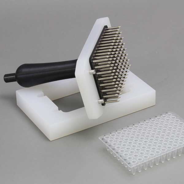
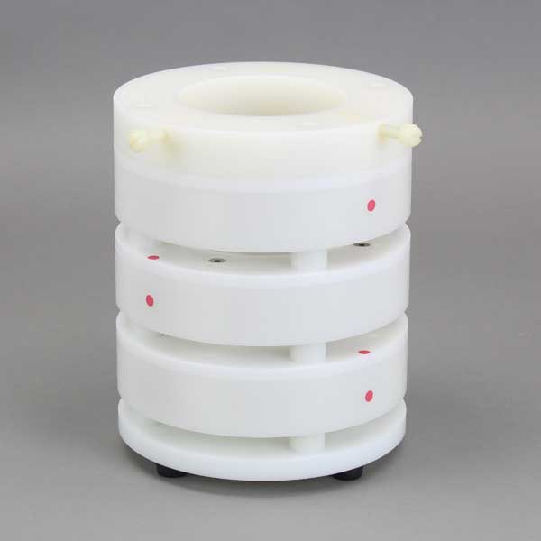
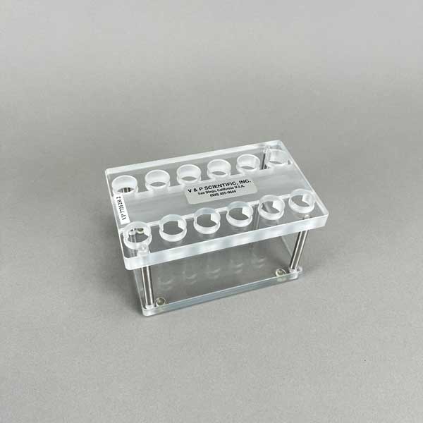
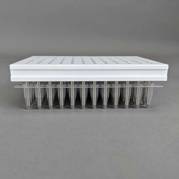
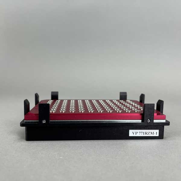
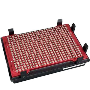
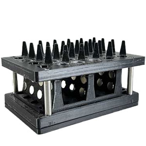
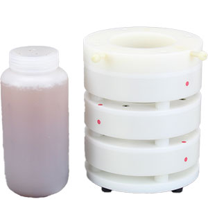
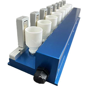
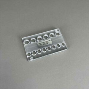
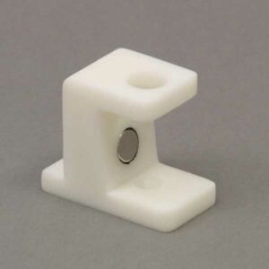
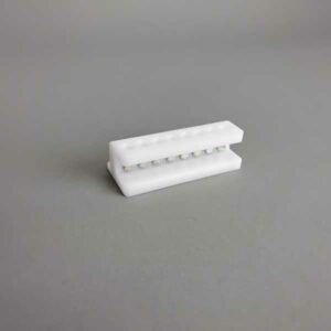
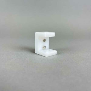
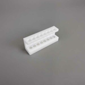
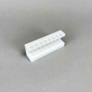
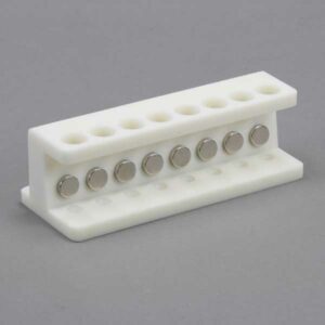
V&P Scientific provides a full line of magnetic bead separation devices for use with magnetic beads in microplates, vials, tubes, bottles, and large containers. V&P has the largest collection of Magnetic Bead Separation devices on the market for all Microplate and PCR models, all types of tube and micro-tube racks, and many bottles stands.
V&P Magnetic Bead separation devices will collect bead pellets at multiple locations around the vessels from the bottom, to one side, to 4 sides, to different levels up the side of the vessel or to both a high and a low position on the side.
V&P Magnetic Separation devices use the strongest magnets and locate them close to the wall of the vessel for the fastest separation times and least bead loss during wash steps. We also control the direction of the magnetic field so it has the maximum capture.
We build custom magnetic Bead Separation devices to match your unique microplate, robotic microplate washer, tube, microtube, or bottle system. If you haven’t already selected the best microplate for your assay, call us for suggestions. We can save you from many unanticipated problems.
It is important to match the right magnet plate with your microplate. There are many different microplate manufacturers and each of them incorporates unique structural features into their plates. Some do a better job at providing a smooth internal well or tube surface than others. Features of the skirt, the shape of the wells, to the injection “gates” under the microplate are very important.
We also consider the magnetic beads or particles you are using. Depending on the size of the beads, and also the concentration, we may suggest a specific product for your application. Naturally, larger magnetic bead particles will separate faster than smaller particles. The larger particles have greater mass which aids in the magnetic bead separation.
Depending on your protocol, you may want the beads to be collected on the side of the wells, or maybe directly in the center. We have several magnetic bead separation devices that will place the beads in different locations. We look at the shape of the wells, volumes, and how you will be removing the supernatant.
More commonly, magnetic beads are separated and then washed using pipette tips. By using pipette tips, it is important to keep the beads away from the pipette. This is why bead location is so important.
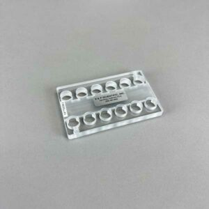
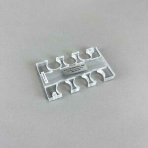
V&P has a large variety of different magnetic bead separation devices for tubes of every size. It is important to match the right magnet device with your tube and where you want the pellet located. If you need assistance or have any questions about our magnet devices, please feel free to contact us.
We also consider the magnetic beads or particles you are using. Depending on the size of the beads, and the concentration, we may suggest a specific product for your application. Naturally, larger magnetic bead particles will separate faster than smaller particles. The larger particles have a greater mass which aids in the magnetic bead separation.
Depending on your protocol, you may want the beads to be collected on the side of the tube, at different height levels, at multiple levels, or maybe directly at the bottom, center, or side of the tube. We have several magnetic bead separation devices that will place the beads in different locations. We look at the height and shape of each tube plus the volume of initial liquid and volume of the elution liquid in your assay protocol and how you will be removing the supernatant.
Aspirate and Dispense:
Most commonly, magnetic beads are pelleted, and then the supernatant is removed by our aspiration manifolds or a pipette and then washed using our dispensing manifolds or by dispensing pipette. It is important to keep the beads away from the aspiration device. Therefore bead collection location is extremely important.
FlicknBlot and Dispense:
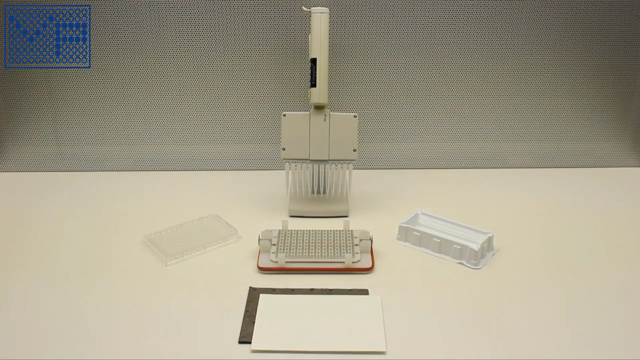
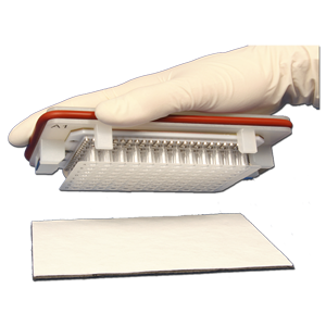
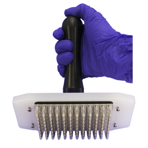
V&P also has a line of hand-held magnetic bead separation devices for tubes. These devices allow for the tubes to be fixed to the magnet rack. You can then pick up the entire device and “Flick” out the supernatant. The tube can then be blotted on our lint-free blotting paper. This is a fast, economical way of removing supernatant from your tubes while still retaining your magnetic beads. These tubes can be washed with our dispensing manifolds.
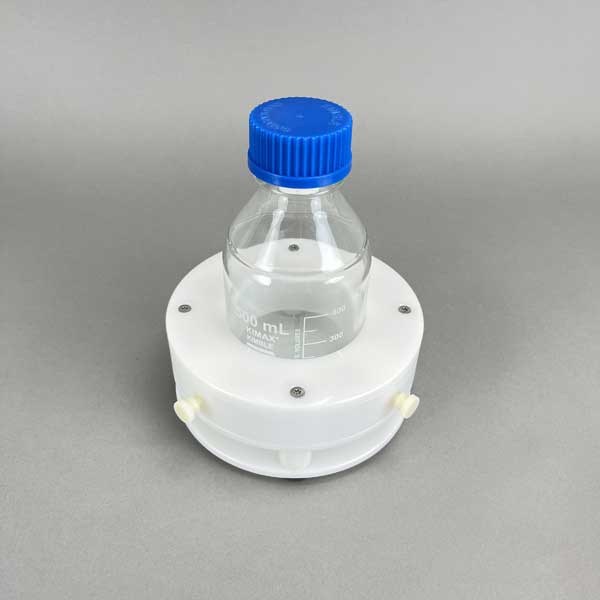
V&P has several magnetic separation stands for bottles 500ml to 1 liter in size and an adjustable Stand that will accommodate Bottles with a diameter up to 73 mm. It is important to match the right magnet device with your bottle and where you want the pellet located. If you need assistance or have any questions about our magnet devices, please feel free to contact us.
There are several ways to wash Magnetic Beads and remove the supernatant without removing beads, (aspirate and dispense, our unique Flick 'N Blot technique, or our MagWash® technique). While these are the more common methods to remove the supernatant from your beads, we also have the VP 407AM-N-1 that will remove the beads from the microplate and transfer them to another microplate for further washing.
“V&P always impresses. Have you seen the V&P Magnets that can convert a multi-channel head to turn your liquid handler into a kingfisher style extraction? Great Products!”
Showing 91–105 of 118 results
Pin | Description | nl Transferred | CV% | |
---|---|---|---|---|
0.229 mm diameter (FP9) | Total Pin | Uncoated | 7.41 | 2.4 |
Hydrophobic | 7.46 | 5.4 | ||
0.229 mm diameter (FP9) | Hanging Drop | Uncoated | N/A | N/A |
Hydrophobic | 2.09 | 3.8 | ||
0.457 mm diameter (FP1) | Total Pin | Uncoated | 33.48 | 3.2 |
Hydrophobic | 28.17 | 7.5 | ||
0.457 mm diameter (FP1) | Hanging Drop | Uncoated | 16.96 | 4.5 |
Hydrophobic | 8.51 | 0.8 | ||
0.787 mm diameter (FP3) | Total Pin | Uncoated | 87.32 | 3.9 |
Hydrophobic | 77.4 | 3.9 | ||
0.787 mm diameter (FP3) | Hanging Drop | Uncoated | 48.77 | 1.2 |
Hydrophobic | 43.05 | 9.4 | ||
1.19 mm diameter (VP 409 & VP 386) | Total Pin | Uncoated | 247.22 | 2.8 |
Hydrophobic | 192.67 | 2.6 | ||
1.19 mm diameter (VP 409 & VP 386) | Hanging Drop | Uncoated | 76.35 | 1.6 |
Hydrophobic | 108.4 | 2.8 | ||
1.58 mm diameter (VP 408 & VP 384) | Total Pin | Uncoated | 273.5 | 4.6 |
Hydrophobic | 259.25 | 3.1 | ||
1.58 mm diameter (VP 408 & VP 384) | Hanging Drop | Uncoated | 201.93 | 5 |
Hydrophobic | 170.04 | 7.5 |
Transfer Of Horseradish Peroxidase In Tris Buffered Saline With Pin Tools
Coating pins will reduce the total amount of liquid transferred and also reduce the amount of non-specific binding to the stainless-steel pins. If the substance you are transferring has high non-specific binding this will be an important factor in selecting your pins.
Pin | Description | nl Transferred | CV% | |
---|---|---|---|---|
0.229 mm diameter (FP9) | Total Pin | Uncoated | 7.41 | 2.4 |
Hydrophobic | 7.46 | 5.4 | ||
0.229 mm diameter (FP9) | Hanging Drop | Uncoated | N/A | N/A |
Hydrophobic | 2.09 | 3.8 | ||
0.457 mm diameter (FP1) | Total Pin | Uncoated | 33.48 | 3.2 |
Hydrophobic | 28.17 | 7.5 | ||
0.457 mm diameter (FP1) | Hanging Drop | Uncoated | 16.96 | 4.5 |
Hydrophobic | 8.51 | 0.8 | ||
0.787 mm diameter (FP3) | Total Pin | Uncoated | 87.32 | 3.9 |
Hydrophobic | 77.4 | 3.9 | ||
0.787 mm diameter (FP3) | Hanging Drop | Uncoated | 48.77 | 1.2 |
Hydrophobic | 43.05 | 9.4 | ||
1.19 mm diameter (VP 409 & VP 386) | Total Pin | Uncoated | 247.22 | 2.8 |
Hydrophobic | 192.67 | 2.6 | ||
1.19 mm diameter (VP 409 & VP 386) | Hanging Drop | Uncoated | 76.35 | 1.6 |
Hydrophobic | 108.4 | 2.8 | ||
1.58 mm diameter (VP 408 & VP 384) | Total Pin | Uncoated | 273.5 | 4.6 |
Hydrophobic | 259.25 | 3.1 | ||
1.58 mm diameter (VP 408 & VP 384) | Hanging Drop | Uncoated | 201.93 | 5 |
Hydrophobic | 170.04 | 7.5 |
Transfer Of Horseradish Peroxidase In Tris Buffered Saline With Pin Tools
Although the slots in the pin are a precise volume, the liquid that is transferred is usually more. The reason for this is due to the surface tension of the liquid causing the liquid in the slot to “bow out” thus increasing the volume of the liquid in the slot. If is important for you to transfer exactly a certain volume we can make custom slots to match the surface tension characteristics of your liquid
Solvent/Sample | Concentration | CV% | nl FITC Transferred | CV% | nl FITC Transferred |
---|---|---|---|---|---|
Uncoated | Uncoated | Hydrophobic Coated | Hydrophobic Coated | ||
DMSO (-) | 0 | 8.1 | 353.42 | 7.5 | 298.72 |
DMSO + DNA (mg/ml) | 0.5 | 6.6 | 497.21 | 6.6 | 435.86 |
0.25 | 9 | 432.49 | 4.1 | 391.93 | |
0.125 | 8.9 | 363.64 | 0.9 | 344.75 | |
0.0625 | 2.3 | 381.86 | 2 | 331.68 | |
0.0313 | 1.5 | 378.03 | 4.4 | 331.71 | |
0.0156 | 1.2 | 357.52 | 1.4 | 329.03 | |
Tris (-) | 0 | 4.9 | 577.31 | 7.2 | 493.53 |
Tris + DNA (mg/ml) | 0.5 | 4.5 | 540.53 | 1.1 | 477.5 |
0.25 | 4.6 | 518.21 | 6.1 | 456.75 | |
0.125 | 15.8 | 583.25 | 4.1 | 438.82 | |
0.0625 | 4.2 | 551.17 | 3.1 | 433.69 | |
0.0313 | 4.4 | 536.66 | 2.3 | 458.37 | |
0.0156 | 2.9 | 528.53 | 1.2 | 441.1 | |
Tris + BSA (%) | 4 | 5.4 | 462.13 | 11 | 409.27 |
1 | 4 | 452.86 | 2.7 | 426.58 | |
0.25 | 11.7 | 456.45 | 1.3 | 408.72 | |
0.0625 | 1.1 | 445.22 | 6.5 | 393.07 | |
0.0156 | 3.7 | 462.85 | 3.9 | 430.2 | |
0.0039 | 1.5 | 493.54 | 2.2 | 437.29 | |
0.001 | 2.9 | 504.25 | 0.7 | 475.96 |
1. Increasing the concentration of DNA (sheared salmon sperm) to .25 mg/ml significantly increases the volume of DMSO liquid transferred for both coated and uncoated FP3S500 Slot Pins.
2. Increasing the concentration of DNA does not significantly increase the volume of Tris buffer (aqueous) transferred by both coated and uncoated FP3S500 Slot Pins.
3. Increasing the concentration of BSA (Bovine Serum Albumin) significantly decreases the volume of Tris buffer transferred by both coated and uncoated FP3S500 Slot Pins.
4. Hydrophobic coated FP3S500 Slot Pins transferred less DMSO – DNA and less Tris DNA and less Tris BSA than the uncoated FP3S500 Slot Pins.
5. Both coated and uncoated FP3S500 pins transfer significantly more aqueous solution than DMSO.
Solvent/Sample | Concentration | CV% | nl FITC Transferred | CV% | nl FITC Transferred |
---|---|---|---|---|---|
Uncoated | Uncoated | Hydrophobic Coated | Hydrophobic Coated | ||
DMSO (-) | 0 | 4.2 | 49.38 | 2.1 | 49.31 |
DMSO + DNA (mg/ml) | 0.5 | 4.9 | 51.24 | 2.6 | 56.79 |
0.25 | 1.7 | 50.2 | 1.2 | 49.53 | |
0.125 | 1.5 | 51.27 | 2.3 | 49.77 | |
0.0625 | 2.2 | 49.34 | 4.1 | 48.19 | |
0.0313 | 1.2 | 49.03 | 0.2 | 50.23 | |
0.0156 | 2.4 | 45.9 | 1.4 | 46.64 | |
Tris (-) | 0 | 2.6 | 89.51 | 2.9 | 91.34 |
Tris + DNA (mg/ml) | 0.5 | 7 | 77.11 | 0.6 | 84.62 |
0.25 | 3.9 | 82.22 | 1.6 | 84.89 | |
0.125 | 3.9 | 85.42 | 1 | 85.08 | |
0.0625 | 1.5 | 85.36 | 2.8 | 85.03 | |
0.0313 | 2 | 84.52 | 3 | 88.19 | |
0.0156 | 2.6 | 82.92 | 2.8 | 83.2 |
1. In contrast to the FP3S500 data, increasing the concentration of DNA to .25 mg/ml does not significantly increase the volume of DMSO liquid transferred for both coated and uncoated FP1S50 Slot Pins.
2. Increasing the concentration of DNA does not significantly increase the volume of Tris buffer (aqueous) transferred by both coated and uncoated FP1S50 Slot Pins.
3. In contrast to the FP3S500 data, FP1S50 coated pins transferred about the same volume of DNA at all concentrations as did uncoated pins.
4. Both coated and uncoated FP1S50 pins transfer significantly more aqueous solution than DMSO.
5. The differences between the FP3S500 and the FP1S50 pin may be due to the different pin diameter’s effect on contact angle and therefore on the “wetting” of the pin. See the diagram on the link to / ah energy system.
Pin | Description | nl Transferred | CV% | |
---|---|---|---|---|
0.229 mm diameter (FP9) | Total Pin | Uncoated | 7.41 | 2.4 |
Hydrophobic | 7.46 | 5.4 | ||
0.229 mm diameter (FP9) | Hanging Drop | Uncoated | N/A | N/A |
Hydrophobic | 2.09 | 3.8 | ||
0.457 mm diameter (FP1) | Total Pin | Uncoated | 33.48 | 3.2 |
Hydrophobic | 28.17 | 7.5 | ||
0.457 mm diameter (FP1) | Hanging Drop | Uncoated | 16.96 | 4.5 |
Hydrophobic | 8.51 | 0.8 | ||
0.787 mm diameter (FP3) | Total Pin | Uncoated | 87.32 | 3.9 |
Hydrophobic | 77.4 | 3.9 | ||
0.787 mm diameter (FP3) | Hanging Drop | Uncoated | 48.77 | 1.2 |
Hydrophobic | 43.05 | 9.4 | ||
1.19 mm diameter (VP 409 & VP 386) | Total Pin | Uncoated | 247.22 | 2.8 |
Hydrophobic | 192.67 | 2.6 | ||
1.19 mm diameter (VP 409 & VP 386) | Hanging Drop | Uncoated | 76.35 | 1.6 |
Hydrophobic | 108.4 | 2.8 | ||
1.58 mm diameter (VP 408 & VP 384) | Total Pin | Uncoated | 273.5 | 4.6 |
Hydrophobic | 259.25 | 3.1 | ||
1.58 mm diameter (VP 408 & VP 384) | Hanging Drop | Uncoated | 201.93 | 5 |
Hydrophobic | 170.04 | 7.5 |
Hydrophobic coating pins will reduce the total amount of aqueous HRP liquid transferred and also reduce the amount of non-specific binding to the stainless-steel pins. If the substance you are transferring has high non-specific binding this will be an important factor in selecting your pins.
Pin diameter also has an effect on the degree of reduction of liquid transfer with hydrophobic coating as the smaller the diameter the less the reduction of transfer. This is most likely due to the curvature of the pin affecting the wetting contact angle
Pin | Description | nl Transferred | CV% | ||
---|---|---|---|---|---|
0.457 mm diameter (FP1) | 6 nl Slot | Total Pin* | Uncoated | 25.6 | 10.8 |
Hydrophobic | N/A | N/A | |||
10 nl Slot | Total Pin* | Uncoated | 23.36 | 6.1 | |
Hydrophobic | 25.85 | 6.9 | |||
50 nl Slot | Total Pin* | Uncoated | 67.83 | 2.5 | |
Hydrophobic | N/A | N/A | |||
0.787 mm diameter (FP3) | 100 nl Slot | Total Pin* | Uncoated | 180.32 | 7.2 |
Hydrophobic | 205.84 | 5.5 | |||
200 nl Slot | Total Pin* | Uncoated | 277.82 | 4.9 | |
Hydrophobic | 287.3 | 3.8 | |||
500 nl Slot | Total Pin* | Uncoated | 581.16 | 5.2 | |
Hydrophobic | 555.69 | 3 |
Hydrophobic coating pins will slightly increase the total amount of DMSO FITC liquid transferred.
Pin | Description | nl Transferred | CV% | |
---|---|---|---|---|
0.787 mm diameter (FP3) | 100 nl Slot Total Pin, Including Slot | Uncoated | 195.69 | 1.6 |
Hydrophobic | 170.2 | 2.9 | ||
0.787 mm diameter (FP3) | 100 nl Slot, Slot Only | Uncoated | 149.67 | 4.9 |
Hydrophobic | 129.61 | 7.6 | ||
0.787 mm diameter (FP3) | 200 nl Slot Total Pin, Including Slot | Uncoated | 269.77 | 1.9 |
Hydrophobic | 228.62 | 17.1 | ||
0.787 mm diameter (FP3) | 200 nl Slot, Slot Only | Uncoated | 237.52 | 8.9 |
Hydrophobic | 186.9 | 5.9 |
Although the slots in the pin are a precise volume, the liquid that is transferred is usually more because of the volume carried on the sides of the pins.
As seen with other aqueous data the amount transferred on hydrophobic coated Slot pins is less than on uncoated Solid or Slot pins. Thus Hydrophobic coating has the most effect on aqueous transfers.
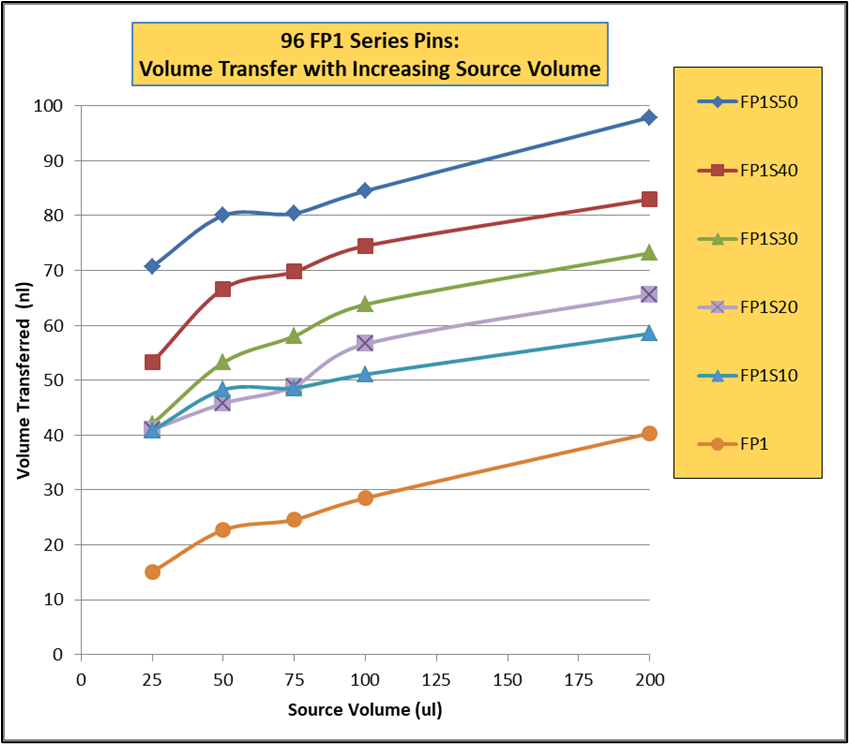
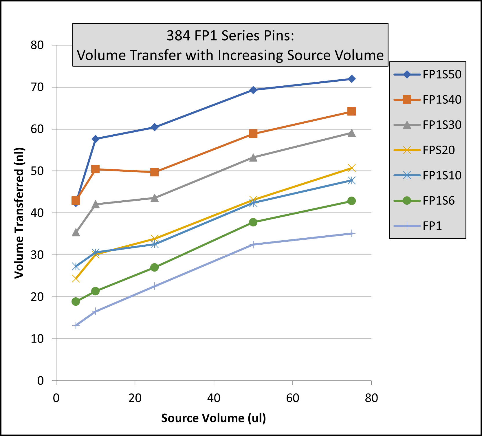
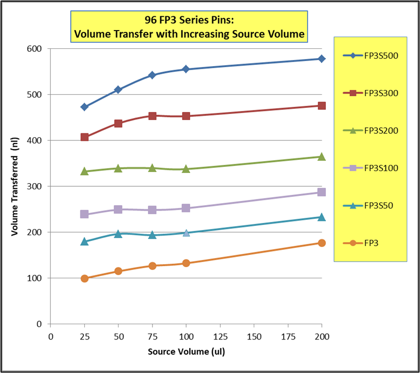
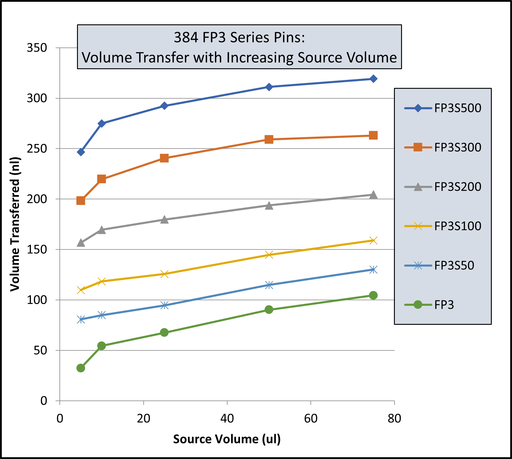
Note: Same volume (200ul for 96 Format and 74 ul for 384 Format) in recipient plates and same pin withdrawal speed for all pins. Changes to pin withdrawal speed or volume in the source plate can result in different volumes being transferred.
Transfer volumes should always be confirmed by customers for their assay conditions and automated system.
Pin Type | Pin Diameter(mm) | Shape | 96 Format Low Range(nL)² | 96 Format High Range(nL)² |
---|---|---|---|---|
FP9 | 0.229 | Solid | 13 | 39 |
FP8 | 0.356 | Solid | 15 | 37 |
FP1 | 0.457 | Solid | 22 | 61 |
FP1S6 | 0.457 | 6nL Slot | 34 | 67 |
FP1S10 | 0.457 | 10nL Slot | 39 | 74 |
FP1S50 | 0.457 | 50nL Slot | 90 | 124 |
FP3 | 0.787 | Solid | 93 | 213 |
FP3S100 | 0.787 | 100nL Slot | 213 | 334 |
FP3S200 | 0.787 | 200nL Slot | 311 | 449 |
FP3S500 | 0.787 | 500nL Slot | 515 | 671 |
FP4 | 0.914 | Solid | 126 | 289 |
Footnotes: (1) Delivery volume range is determined by speed of withdrawal from source liquid: Z-Speed Range = 1.5-30 mm/sec, slow speed = low volume delivery range, fast speed = high volume delivery range (2) 200ul source plate volume per well |
Pin Type | Pin Diameter(mm) | Shape | 96 Format Low Range(nL)² | 96 Format High Range(nL)² |
---|---|---|---|---|
FP9 | 0.229 | Solid | 13 | 38 |
FP8 | 0.356 | Solid | ||
FP1 | 0.457 | Solid | 23 | 60 |
FP1S6 | 0.457 | 6nL Slot | 33 | 67 |
FP1S10 | 0.457 | 10nL Slot | 40 | 75 |
FP1S50 | 0.457 | 50nL Slot | 86 | 119 |
FP3 | 0.787 | Solid | 76 | 209 |
FP3S100 | 0.787 | 100nL Slot | 188 | 324 |
FP3S200 | 0.787 | 200nL Slot | 288 | 436 |
FP3S500 | 0.787 | 500nL Slot | 473 | 649 |
FP4 | 0.914 | Solid | ||
Footnotes: (1) Delivery volume range is determined by speed of withdrawal from source liquid: Z-Speed Range = 1.5-30 mm/sec, slow speed = low volume delivery range, fast speed = high volume delivery range (2) 200ul source plate volume per well |
Pin Type | Pin Diameter(mm) | Shape | Low Range(nL)² | High Range(nL)² |
---|---|---|---|---|
FP | 1.58 | Solid Pointed | 175 | 594 |
FPS.5 | 1.58 | 500nL Slot | 524 | 962 |
FPS | 1.58 | 1000nL Slot | 1056 | 1476 |
FPS2 | 1.58 | 2000nL Slot | 1739 | 2174 |
FPS5 | 1.58 | 5000nL Slot | 5150 | 4953 |
FP6 | 1.58 | Solid Flat | 465 | 960 |
FP6S.5 | 1.58 | 500nL Slot | 934 | 1445 |
FP6S | 1.58 | 1000nL Slot | 1396 | 1930 |
FP6S2 | 1.58 | 2000nL Slot | 2072 | 2637 |
FP6S5 | 1.58 | 5000nL Slot | 4820 | 4693 |
Footnotes:(1) Delivery volume range is determined by speed of withdrawal from source liquid: Z-Speed Range = 1.5-30 mm/sec, slow speed = low volume delivery range, fast speed = high volume delivery range (2) 200ul source plate volume per well for 96 Format and 75ul source plate volume per well for 384 Format |
Pin Type | Pin Diameter(mm) | Shape | 96 Format Low Range(nL)² | 96 Format High Range(nL)² | 384 Format Low Range(nL)³ | 384 Format High Range(nL)³ |
---|---|---|---|---|---|---|
FP9 | 0.229 | Solid | 4 | 10 | 3 | 8 |
FP8 | 0.35 | Solid | 13 | 26 | 6 | 18 |
FP1 | 0.457 | Solid | 18 | 43 | 11 | 31 |
FP1S6 | 0.457 | 6nL Slot | 24 | 49 | 15 | 34 |
FP1S10 | 0.457 | 10nL Slot | 30 | 54 | 21 | 40 |
FP1S20 | 0.457 | 20nL Slot | 37 | 61 | 27 | 46 |
FP1S30 | 0.457 | 30nL Slot | 46 | 68 | 35 | 54 |
FP1S40 | 0.457 | 40nL Slot | 57 | 78 | 45 | 63 |
FP1S50 | 0.457 | 50nL Slot | 70 | 90 | 56 | 75 |
FP3 | 0.787 | Solid | 67 | 139 | 29 | 79 |
FP4 | 0.91 | Solid | 94 | 197 | 34 | 98 |
FP3S100 | 0.787 | 100nL Slot | 175 | 241 | 114 | 163 |
FP3S200 | 0.787 | 200nL Slot | 280 | 332 | 203 | 250 |
FP3S500 | 0.787 | 500nL Slot | 535 | 559 | 427 | 464 |
FP4S1000 | 0.91 | 1000nL Slot | 940 | 1011 | 704 | 800 |
FP4S2000 | 0.91 | 2000nL Slot | 1518 | 1608 | 1277 | 1362 |
Footnotes: (1) Delivery volume range is determined by speed of withdrawal from source liquid: Z-Speed Range = 1.5-30 mm/sec, slow speed = low volume delivery range, fast speed = high volume delivery range (2) 200ul source plate volume per well (3) 75ul source plate volume per well |
Pin Type | Pin Diameter (mm) | Shape | 96 Format Low Range(nL)² | 96 Format High Range(nL)² | 384 Format Low Range(nL)³ | 384 Format High Range(nL)³ |
---|---|---|---|---|---|---|
FP9H | 0.229 | Solid | 4 | 10 | 3 | 8 |
FP8H | 0.35 | Solid | 9 | 24 | 6 | 17 |
FP1H | 0.457 | Solid | 15 | 39 | 9 | 27 |
FP1S6H | 0.457 | 6nL Slot | 23 | 49 | 14 | 32 |
FP1S10H | 0.457 | 10nL Slot | 29 | 53 | 20 | 38 |
FP1S20H | 0.457 | 20nL Slot | 35 | 59 | 26 | 43 |
FP1S30H | 0.457 | 30nL Slot | 47 | 69 | 35 | 53 |
FP1S40H | 0.457 | 40nL Slot | 54 | 75 | 41 | 58 |
FP1S50H | 0.457 | 50nL Slot | 69 | 90 | 57 | 73 |
FP3H | 0.787 | Solid | 67 | 134 | 27 | 76 |
FP4H | 0.91 | Solid | 95 | 189 | 32 | 102 |
FP3S100H | 0.787 | 100nL Slot | 170 | 227 | 108 | 164 |
FP3S200H | 0.787 | 200nL Slot | 266 | 320 | 190 | 239 |
FP3S500H | 0.787 | 500nL Slot | 520 | 542 | 416 | 456 |
FP4S1000H | 0.91 | 1000nL Slot | 932 | 1000 | 741 | 805 |
FP4S2000H | 0.91 | 2000nL Slot | 1571 | 1638 | 1351 | 1423 |
Footnotes: (1) Delivery volume range is determined by speed of withdrawal from source liquid: Z-Speed Range = 1.5-30 mm/sec, slow speed = low volume delivery range, fast speed = high volume delivery range (2) 200ul source plate volume per well (3) 75ul source plate volume per well |
Pin Type | Diameter (mm) | Shape | 96 Format Low Range(nL)² | 96 Format High Range(nL)² | 384 Format Low Range(nL)³ | 384 Format High Range(nL)³ |
---|---|---|---|---|---|---|
FP | 1.58 | Solid Pointed | 147 | 411 | 168 | 395 |
FPS.5 | 1.58 | 500nL Slot | 442 | 704 | 631 | 843 |
FPS | 1.58 | 1000nL Slot | 893 | 1130 | 1343 | 1498 |
FPS2 | 1.58 | 2000nL Slot | 1911 | 2038 | 2607 | 2767 |
FPS5 | 1.58 | 5000nL Slot | 3908 | 4296 | 5180 | 5253 |
FP6 | 1.58 | Solid Flat | 323 | 674 | 154 | 398 |
FP6S.5 | 1.58 | 500nL Slot | 734 | 1042 | 855 | 1053 |
FP6S | 1.58 | 1000nL Slot | 1210 | 1500 | 1638 | 1717 |
FP6S2 | 1.58 | 2000nL Slot | 2299 | 2384 | 2787 | 3068 |
FP6S5 | 1.58 | 5000nL Slot | 4329 | 4656 | 5237 | 5245 |
Footnotes:(1) Delivery volume range is determined by speed of withdrawal from source liquid: Z-Speed Range = 1.5-30 mm/sec, slow speed = low volume delivery range, fast speed = high volume delivery range (2) 200ul source plate volume per well (3) 75ul source plate volume per well |