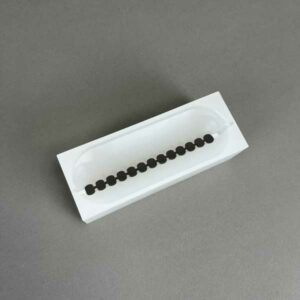
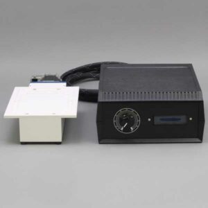
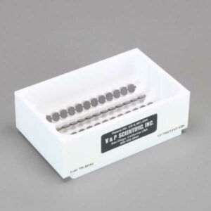
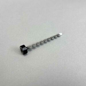
BUBBLE PADDLE RESERVIOR, Tumble Powered, 12 Channel, Polypropylene Reservoir, with 1 Bubble Paddle, Parylene Coated, 13 Bubbles/Paddle, with 2 PTFE Hubs, Mixes 70mL
BUBBLE PADDLE RESERVIOR, Tumble Powered, 12 Channel, Polypropylene, Mates to VP 710C Series
BUBBLE PADDLE RESERVIOR, Tumble Powered, 12 Channel, Polypropylene Reservoir, with 1 Bubble Paddle, Parylene Coated, 13 Bubbles/Paddle, with 2 PTFE Hubs, Mixes 70mL
Drive System | Tumble Stirrer |
---|---|
Pipette Head Format | 12 |
Material | Polypropylene |
No of Bubble Paddles | 1 |
Bubbles/Paddle | 13 |
Encapsulation/Coating | Parylene |
Volume | 70mL |
SLAS Base | No |
V&P has developed over 30 different reservoir suspension systems for pipetting uniformly suspended beads, cells, particles, and resins into microplates of nearly every description. We have refined, perfected, and consolidated that list down to the best 22. These reservoir suspension systems are powered by one of our 15 different Vertical Tumble Stirrers.
Keeping magnetic beads, assay beads, SPA beads, glass beads, resins other particulates, and cells in homogeneous suspension while they are being pipetted to microplate wells is very important if reproducible results are to be obtained. It is also important to do this with the smallest dead volume possible when the reagents are very expensive. Although one might think you cannot use magnets to stir and suspend magnetic beads, V&P has found a way to uniformly suspend magnetic beads with our parylene-coated suspension systems and Magnetic Vertical Tumble Stirrers.
The unique V&P Scientific Bubble Paddle Reservoir suspension systems (US Patent #6,461,034 & European Union Patent #1,314,471) provide a very simple and inexpensive way of accomplishing this goal. Whether you are using a 4, 8, 16, 24, 96, or 384 pipetting head, there is a suspension reservoir with a bubble spacing that allows a pipette tip to be inserted in the gap between bubbles. The unique contours machined into the reservoir coupled with the contours of the Bubble Paddle design results in very vigorous stirring and homogeneous suspension of the particulate contents in the reservoir. The unique feature of the Bubble Paddle Reservoirs is their exclusive design that eliminates “fall out zones” where particulates fall out of solution that is so prevalent with other mixing reservoirs. Also if dead volume is not an issue in your assay you can use our economical VP 756B-4PPP suspension reservoir powered by a VP 710D3 Tumble Stirrer in conjunction with a 4, 8, or 16 pipette head for a low-cost reservoir suspension system.
There are many characteristics of your material that will affect where and how they are suspended:
All of the features above are very important; choose your suspension system wisely before you launch a new assay protocol. We have dealt with it all in the last 30 years. With our large selection of Suspension Reservoirs Systems, we can help you make the best decision for your application. We are happy to share our knowledge with you.
We discovered that by using parylene-coated bubble paddles with Vertical Tumble Stirrers, we could easily keep magnetic beads in uniform suspension and the magnetic beads would not remain attracted to the parylene-coated bubble paddles, or stay on the bottom of the reservoir once the paddles begin to move. This greatly expands the number of systems possible for a magnetic bead application, furthermore, it simplifies and reduces the cost of the magnetic bead suspension systems:
If economy and uniformity of suspension are important to you, we have solutions for you.
V&P’s patented contours in the bottom of the reservoir which match the contours of the Bubble Paddles produce a vigorous upwelling current in the reservoirs to keep particulates in uniform suspension.
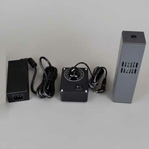
See Vertical Tumble Stirrers that power our Suspension Reservoir Systems.
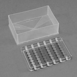
See our other accessories for Suspension Reservoirs.
Keep any non-magnetic particulate in homogeneous suspension for pipetting of equal particle quantities into microplates or vials. There’s an endless amount of possible applications. |
|
Our Suspension Reservoir Systems accommodate many pipetting robots and can also be used on the bench top with manual with either single, 8 or 12 channel pipets. |
|
Our specialized Suspension Reservoir Systems can be used in a variety of different environments, and with unique liquids. |
|
Pin | Description | nl Transferred | CV% | |
---|---|---|---|---|
0.229 mm diameter (FP9) | Total Pin | Uncoated | 7.41 | 2.4 |
Hydrophobic | 7.46 | 5.4 | ||
0.229 mm diameter (FP9) | Hanging Drop | Uncoated | N/A | N/A |
Hydrophobic | 2.09 | 3.8 | ||
0.457 mm diameter (FP1) | Total Pin | Uncoated | 33.48 | 3.2 |
Hydrophobic | 28.17 | 7.5 | ||
0.457 mm diameter (FP1) | Hanging Drop | Uncoated | 16.96 | 4.5 |
Hydrophobic | 8.51 | 0.8 | ||
0.787 mm diameter (FP3) | Total Pin | Uncoated | 87.32 | 3.9 |
Hydrophobic | 77.4 | 3.9 | ||
0.787 mm diameter (FP3) | Hanging Drop | Uncoated | 48.77 | 1.2 |
Hydrophobic | 43.05 | 9.4 | ||
1.19 mm diameter (VP 409 & VP 386) | Total Pin | Uncoated | 247.22 | 2.8 |
Hydrophobic | 192.67 | 2.6 | ||
1.19 mm diameter (VP 409 & VP 386) | Hanging Drop | Uncoated | 76.35 | 1.6 |
Hydrophobic | 108.4 | 2.8 | ||
1.58 mm diameter (VP 408 & VP 384) | Total Pin | Uncoated | 273.5 | 4.6 |
Hydrophobic | 259.25 | 3.1 | ||
1.58 mm diameter (VP 408 & VP 384) | Hanging Drop | Uncoated | 201.93 | 5 |
Hydrophobic | 170.04 | 7.5 |
Transfer Of Horseradish Peroxidase In Tris Buffered Saline With Pin Tools
Coating pins will reduce the total amount of liquid transferred and also reduce the amount of non-specific binding to the stainless-steel pins. If the substance you are transferring has high non-specific binding this will be an important factor in selecting your pins.
Pin | Description | nl Transferred | CV% | |
---|---|---|---|---|
0.229 mm diameter (FP9) | Total Pin | Uncoated | 7.41 | 2.4 |
Hydrophobic | 7.46 | 5.4 | ||
0.229 mm diameter (FP9) | Hanging Drop | Uncoated | N/A | N/A |
Hydrophobic | 2.09 | 3.8 | ||
0.457 mm diameter (FP1) | Total Pin | Uncoated | 33.48 | 3.2 |
Hydrophobic | 28.17 | 7.5 | ||
0.457 mm diameter (FP1) | Hanging Drop | Uncoated | 16.96 | 4.5 |
Hydrophobic | 8.51 | 0.8 | ||
0.787 mm diameter (FP3) | Total Pin | Uncoated | 87.32 | 3.9 |
Hydrophobic | 77.4 | 3.9 | ||
0.787 mm diameter (FP3) | Hanging Drop | Uncoated | 48.77 | 1.2 |
Hydrophobic | 43.05 | 9.4 | ||
1.19 mm diameter (VP 409 & VP 386) | Total Pin | Uncoated | 247.22 | 2.8 |
Hydrophobic | 192.67 | 2.6 | ||
1.19 mm diameter (VP 409 & VP 386) | Hanging Drop | Uncoated | 76.35 | 1.6 |
Hydrophobic | 108.4 | 2.8 | ||
1.58 mm diameter (VP 408 & VP 384) | Total Pin | Uncoated | 273.5 | 4.6 |
Hydrophobic | 259.25 | 3.1 | ||
1.58 mm diameter (VP 408 & VP 384) | Hanging Drop | Uncoated | 201.93 | 5 |
Hydrophobic | 170.04 | 7.5 |
Transfer Of Horseradish Peroxidase In Tris Buffered Saline With Pin Tools
Although the slots in the pin are a precise volume, the liquid that is transferred is usually more. The reason for this is due to the surface tension of the liquid causing the liquid in the slot to “bow out” thus increasing the volume of the liquid in the slot. If is important for you to transfer exactly a certain volume we can make custom slots to match the surface tension characteristics of your liquid
Solvent/Sample | Concentration | CV% | nl FITC Transferred | CV% | nl FITC Transferred |
---|---|---|---|---|---|
Uncoated | Uncoated | Hydrophobic Coated | Hydrophobic Coated | ||
DMSO (-) | 0 | 8.1 | 353.42 | 7.5 | 298.72 |
DMSO + DNA (mg/ml) | 0.5 | 6.6 | 497.21 | 6.6 | 435.86 |
0.25 | 9 | 432.49 | 4.1 | 391.93 | |
0.125 | 8.9 | 363.64 | 0.9 | 344.75 | |
0.0625 | 2.3 | 381.86 | 2 | 331.68 | |
0.0313 | 1.5 | 378.03 | 4.4 | 331.71 | |
0.0156 | 1.2 | 357.52 | 1.4 | 329.03 | |
Tris (-) | 0 | 4.9 | 577.31 | 7.2 | 493.53 |
Tris + DNA (mg/ml) | 0.5 | 4.5 | 540.53 | 1.1 | 477.5 |
0.25 | 4.6 | 518.21 | 6.1 | 456.75 | |
0.125 | 15.8 | 583.25 | 4.1 | 438.82 | |
0.0625 | 4.2 | 551.17 | 3.1 | 433.69 | |
0.0313 | 4.4 | 536.66 | 2.3 | 458.37 | |
0.0156 | 2.9 | 528.53 | 1.2 | 441.1 | |
Tris + BSA (%) | 4 | 5.4 | 462.13 | 11 | 409.27 |
1 | 4 | 452.86 | 2.7 | 426.58 | |
0.25 | 11.7 | 456.45 | 1.3 | 408.72 | |
0.0625 | 1.1 | 445.22 | 6.5 | 393.07 | |
0.0156 | 3.7 | 462.85 | 3.9 | 430.2 | |
0.0039 | 1.5 | 493.54 | 2.2 | 437.29 | |
0.001 | 2.9 | 504.25 | 0.7 | 475.96 |
1. Increasing the concentration of DNA (sheared salmon sperm) to .25 mg/ml significantly increases the volume of DMSO liquid transferred for both coated and uncoated FP3S500 Slot Pins.
2. Increasing the concentration of DNA does not significantly increase the volume of Tris buffer (aqueous) transferred by both coated and uncoated FP3S500 Slot Pins.
3. Increasing the concentration of BSA (Bovine Serum Albumin) significantly decreases the volume of Tris buffer transferred by both coated and uncoated FP3S500 Slot Pins.
4. Hydrophobic coated FP3S500 Slot Pins transferred less DMSO – DNA and less Tris DNA and less Tris BSA than the uncoated FP3S500 Slot Pins.
5. Both coated and uncoated FP3S500 pins transfer significantly more aqueous solution than DMSO.
Solvent/Sample | Concentration | CV% | nl FITC Transferred | CV% | nl FITC Transferred |
---|---|---|---|---|---|
Uncoated | Uncoated | Hydrophobic Coated | Hydrophobic Coated | ||
DMSO (-) | 0 | 4.2 | 49.38 | 2.1 | 49.31 |
DMSO + DNA (mg/ml) | 0.5 | 4.9 | 51.24 | 2.6 | 56.79 |
0.25 | 1.7 | 50.2 | 1.2 | 49.53 | |
0.125 | 1.5 | 51.27 | 2.3 | 49.77 | |
0.0625 | 2.2 | 49.34 | 4.1 | 48.19 | |
0.0313 | 1.2 | 49.03 | 0.2 | 50.23 | |
0.0156 | 2.4 | 45.9 | 1.4 | 46.64 | |
Tris (-) | 0 | 2.6 | 89.51 | 2.9 | 91.34 |
Tris + DNA (mg/ml) | 0.5 | 7 | 77.11 | 0.6 | 84.62 |
0.25 | 3.9 | 82.22 | 1.6 | 84.89 | |
0.125 | 3.9 | 85.42 | 1 | 85.08 | |
0.0625 | 1.5 | 85.36 | 2.8 | 85.03 | |
0.0313 | 2 | 84.52 | 3 | 88.19 | |
0.0156 | 2.6 | 82.92 | 2.8 | 83.2 |
1. In contrast to the FP3S500 data, increasing the concentration of DNA to .25 mg/ml does not significantly increase the volume of DMSO liquid transferred for both coated and uncoated FP1S50 Slot Pins.
2. Increasing the concentration of DNA does not significantly increase the volume of Tris buffer (aqueous) transferred by both coated and uncoated FP1S50 Slot Pins.
3. In contrast to the FP3S500 data, FP1S50 coated pins transferred about the same volume of DNA at all concentrations as did uncoated pins.
4. Both coated and uncoated FP1S50 pins transfer significantly more aqueous solution than DMSO.
5. The differences between the FP3S500 and the FP1S50 pin may be due to the different pin diameter’s effect on contact angle and therefore on the “wetting” of the pin. See the diagram on the link to / ah energy system.
Pin | Description | nl Transferred | CV% | |
---|---|---|---|---|
0.229 mm diameter (FP9) | Total Pin | Uncoated | 7.41 | 2.4 |
Hydrophobic | 7.46 | 5.4 | ||
0.229 mm diameter (FP9) | Hanging Drop | Uncoated | N/A | N/A |
Hydrophobic | 2.09 | 3.8 | ||
0.457 mm diameter (FP1) | Total Pin | Uncoated | 33.48 | 3.2 |
Hydrophobic | 28.17 | 7.5 | ||
0.457 mm diameter (FP1) | Hanging Drop | Uncoated | 16.96 | 4.5 |
Hydrophobic | 8.51 | 0.8 | ||
0.787 mm diameter (FP3) | Total Pin | Uncoated | 87.32 | 3.9 |
Hydrophobic | 77.4 | 3.9 | ||
0.787 mm diameter (FP3) | Hanging Drop | Uncoated | 48.77 | 1.2 |
Hydrophobic | 43.05 | 9.4 | ||
1.19 mm diameter (VP 409 & VP 386) | Total Pin | Uncoated | 247.22 | 2.8 |
Hydrophobic | 192.67 | 2.6 | ||
1.19 mm diameter (VP 409 & VP 386) | Hanging Drop | Uncoated | 76.35 | 1.6 |
Hydrophobic | 108.4 | 2.8 | ||
1.58 mm diameter (VP 408 & VP 384) | Total Pin | Uncoated | 273.5 | 4.6 |
Hydrophobic | 259.25 | 3.1 | ||
1.58 mm diameter (VP 408 & VP 384) | Hanging Drop | Uncoated | 201.93 | 5 |
Hydrophobic | 170.04 | 7.5 |
Hydrophobic coating pins will reduce the total amount of aqueous HRP liquid transferred and also reduce the amount of non-specific binding to the stainless-steel pins. If the substance you are transferring has high non-specific binding this will be an important factor in selecting your pins.
Pin diameter also has an effect on the degree of reduction of liquid transfer with hydrophobic coating as the smaller the diameter the less the reduction of transfer. This is most likely due to the curvature of the pin affecting the wetting contact angle
Pin | Description | nl Transferred | CV% | ||
---|---|---|---|---|---|
0.457 mm diameter (FP1) | 6 nl Slot | Total Pin* | Uncoated | 25.6 | 10.8 |
Hydrophobic | N/A | N/A | |||
10 nl Slot | Total Pin* | Uncoated | 23.36 | 6.1 | |
Hydrophobic | 25.85 | 6.9 | |||
50 nl Slot | Total Pin* | Uncoated | 67.83 | 2.5 | |
Hydrophobic | N/A | N/A | |||
0.787 mm diameter (FP3) | 100 nl Slot | Total Pin* | Uncoated | 180.32 | 7.2 |
Hydrophobic | 205.84 | 5.5 | |||
200 nl Slot | Total Pin* | Uncoated | 277.82 | 4.9 | |
Hydrophobic | 287.3 | 3.8 | |||
500 nl Slot | Total Pin* | Uncoated | 581.16 | 5.2 | |
Hydrophobic | 555.69 | 3 |
Hydrophobic coating pins will slightly increase the total amount of DMSO FITC liquid transferred.
Pin | Description | nl Transferred | CV% | |
---|---|---|---|---|
0.787 mm diameter (FP3) | 100 nl Slot Total Pin, Including Slot | Uncoated | 195.69 | 1.6 |
Hydrophobic | 170.2 | 2.9 | ||
0.787 mm diameter (FP3) | 100 nl Slot, Slot Only | Uncoated | 149.67 | 4.9 |
Hydrophobic | 129.61 | 7.6 | ||
0.787 mm diameter (FP3) | 200 nl Slot Total Pin, Including Slot | Uncoated | 269.77 | 1.9 |
Hydrophobic | 228.62 | 17.1 | ||
0.787 mm diameter (FP3) | 200 nl Slot, Slot Only | Uncoated | 237.52 | 8.9 |
Hydrophobic | 186.9 | 5.9 |
Although the slots in the pin are a precise volume, the liquid that is transferred is usually more because of the volume carried on the sides of the pins.
As seen with other aqueous data the amount transferred on hydrophobic coated Slot pins is less than on uncoated Solid or Slot pins. Thus Hydrophobic coating has the most effect on aqueous transfers.
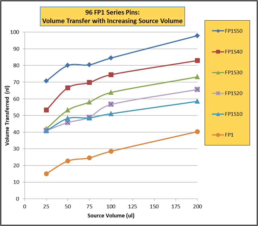
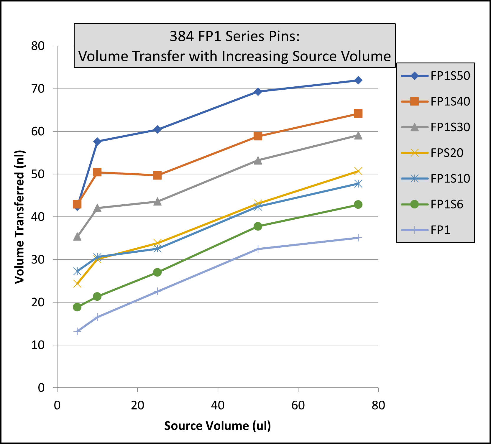
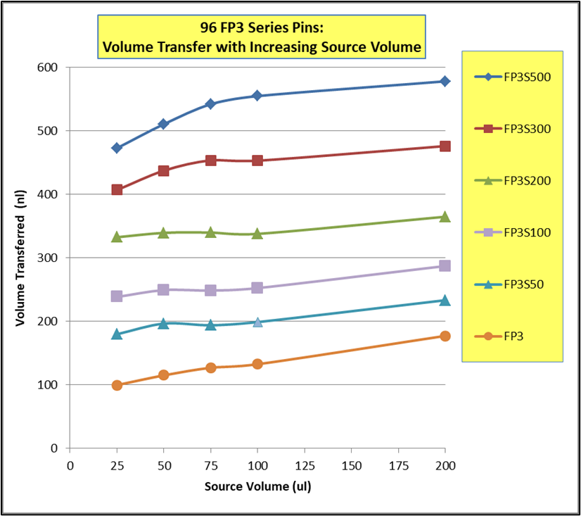
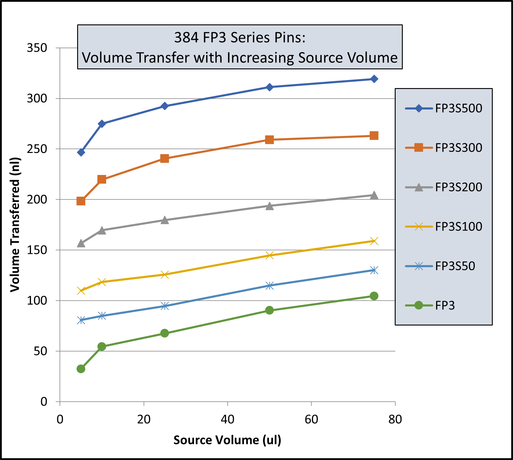
Note: Same volume (200ul for 96 Format and 74 ul for 384 Format) in recipient plates and same pin withdrawal speed for all pins. Changes to pin withdrawal speed or volume in the source plate can result in different volumes being transferred.
Transfer volumes should always be confirmed by customers for their assay conditions and automated system.
Pin Type | Pin Diameter(mm) | Shape | 96 Format Low Range(nL)² | 96 Format High Range(nL)² |
---|---|---|---|---|
FP9 | 0.229 | Solid | 13 | 39 |
FP8 | 0.356 | Solid | 15 | 37 |
FP1 | 0.457 | Solid | 22 | 61 |
FP1S6 | 0.457 | 6nL Slot | 34 | 67 |
FP1S10 | 0.457 | 10nL Slot | 39 | 74 |
FP1S50 | 0.457 | 50nL Slot | 90 | 124 |
FP3 | 0.787 | Solid | 93 | 213 |
FP3S100 | 0.787 | 100nL Slot | 213 | 334 |
FP3S200 | 0.787 | 200nL Slot | 311 | 449 |
FP3S500 | 0.787 | 500nL Slot | 515 | 671 |
FP4 | 0.914 | Solid | 126 | 289 |
Footnotes: (1) Delivery volume range is determined by speed of withdrawal from source liquid: Z-Speed Range = 1.5-30 mm/sec, slow speed = low volume delivery range, fast speed = high volume delivery range (2) 200ul source plate volume per well |
Pin Type | Pin Diameter(mm) | Shape | 96 Format Low Range(nL)² | 96 Format High Range(nL)² |
---|---|---|---|---|
FP9 | 0.229 | Solid | 13 | 38 |
FP8 | 0.356 | Solid | ||
FP1 | 0.457 | Solid | 23 | 60 |
FP1S6 | 0.457 | 6nL Slot | 33 | 67 |
FP1S10 | 0.457 | 10nL Slot | 40 | 75 |
FP1S50 | 0.457 | 50nL Slot | 86 | 119 |
FP3 | 0.787 | Solid | 76 | 209 |
FP3S100 | 0.787 | 100nL Slot | 188 | 324 |
FP3S200 | 0.787 | 200nL Slot | 288 | 436 |
FP3S500 | 0.787 | 500nL Slot | 473 | 649 |
FP4 | 0.914 | Solid | ||
Footnotes: (1) Delivery volume range is determined by speed of withdrawal from source liquid: Z-Speed Range = 1.5-30 mm/sec, slow speed = low volume delivery range, fast speed = high volume delivery range (2) 200ul source plate volume per well |
Pin Type | Pin Diameter(mm) | Shape | Low Range(nL)² | High Range(nL)² |
---|---|---|---|---|
FP | 1.58 | Solid Pointed | 175 | 594 |
FPS.5 | 1.58 | 500nL Slot | 524 | 962 |
FPS | 1.58 | 1000nL Slot | 1056 | 1476 |
FPS2 | 1.58 | 2000nL Slot | 1739 | 2174 |
FPS5 | 1.58 | 5000nL Slot | 5150 | 4953 |
FP6 | 1.58 | Solid Flat | 465 | 960 |
FP6S.5 | 1.58 | 500nL Slot | 934 | 1445 |
FP6S | 1.58 | 1000nL Slot | 1396 | 1930 |
FP6S2 | 1.58 | 2000nL Slot | 2072 | 2637 |
FP6S5 | 1.58 | 5000nL Slot | 4820 | 4693 |
Footnotes:(1) Delivery volume range is determined by speed of withdrawal from source liquid: Z-Speed Range = 1.5-30 mm/sec, slow speed = low volume delivery range, fast speed = high volume delivery range (2) 200ul source plate volume per well for 96 Format and 75ul source plate volume per well for 384 Format |
Pin Type | Pin Diameter(mm) | Shape | 96 Format Low Range(nL)² | 96 Format High Range(nL)² | 384 Format Low Range(nL)³ | 384 Format High Range(nL)³ |
---|---|---|---|---|---|---|
FP9 | 0.229 | Solid | 4 | 10 | 3 | 8 |
FP8 | 0.35 | Solid | 13 | 26 | 6 | 18 |
FP1 | 0.457 | Solid | 18 | 43 | 11 | 31 |
FP1S6 | 0.457 | 6nL Slot | 24 | 49 | 15 | 34 |
FP1S10 | 0.457 | 10nL Slot | 30 | 54 | 21 | 40 |
FP1S20 | 0.457 | 20nL Slot | 37 | 61 | 27 | 46 |
FP1S30 | 0.457 | 30nL Slot | 46 | 68 | 35 | 54 |
FP1S40 | 0.457 | 40nL Slot | 57 | 78 | 45 | 63 |
FP1S50 | 0.457 | 50nL Slot | 70 | 90 | 56 | 75 |
FP3 | 0.787 | Solid | 67 | 139 | 29 | 79 |
FP4 | 0.91 | Solid | 94 | 197 | 34 | 98 |
FP3S100 | 0.787 | 100nL Slot | 175 | 241 | 114 | 163 |
FP3S200 | 0.787 | 200nL Slot | 280 | 332 | 203 | 250 |
FP3S500 | 0.787 | 500nL Slot | 535 | 559 | 427 | 464 |
FP4S1000 | 0.91 | 1000nL Slot | 940 | 1011 | 704 | 800 |
FP4S2000 | 0.91 | 2000nL Slot | 1518 | 1608 | 1277 | 1362 |
Footnotes: (1) Delivery volume range is determined by speed of withdrawal from source liquid: Z-Speed Range = 1.5-30 mm/sec, slow speed = low volume delivery range, fast speed = high volume delivery range (2) 200ul source plate volume per well (3) 75ul source plate volume per well |
Pin Type | Pin Diameter (mm) | Shape | 96 Format Low Range(nL)² | 96 Format High Range(nL)² | 384 Format Low Range(nL)³ | 384 Format High Range(nL)³ |
---|---|---|---|---|---|---|
FP9H | 0.229 | Solid | 4 | 10 | 3 | 8 |
FP8H | 0.35 | Solid | 9 | 24 | 6 | 17 |
FP1H | 0.457 | Solid | 15 | 39 | 9 | 27 |
FP1S6H | 0.457 | 6nL Slot | 23 | 49 | 14 | 32 |
FP1S10H | 0.457 | 10nL Slot | 29 | 53 | 20 | 38 |
FP1S20H | 0.457 | 20nL Slot | 35 | 59 | 26 | 43 |
FP1S30H | 0.457 | 30nL Slot | 47 | 69 | 35 | 53 |
FP1S40H | 0.457 | 40nL Slot | 54 | 75 | 41 | 58 |
FP1S50H | 0.457 | 50nL Slot | 69 | 90 | 57 | 73 |
FP3H | 0.787 | Solid | 67 | 134 | 27 | 76 |
FP4H | 0.91 | Solid | 95 | 189 | 32 | 102 |
FP3S100H | 0.787 | 100nL Slot | 170 | 227 | 108 | 164 |
FP3S200H | 0.787 | 200nL Slot | 266 | 320 | 190 | 239 |
FP3S500H | 0.787 | 500nL Slot | 520 | 542 | 416 | 456 |
FP4S1000H | 0.91 | 1000nL Slot | 932 | 1000 | 741 | 805 |
FP4S2000H | 0.91 | 2000nL Slot | 1571 | 1638 | 1351 | 1423 |
Footnotes: (1) Delivery volume range is determined by speed of withdrawal from source liquid: Z-Speed Range = 1.5-30 mm/sec, slow speed = low volume delivery range, fast speed = high volume delivery range (2) 200ul source plate volume per well (3) 75ul source plate volume per well |
Pin Type | Diameter (mm) | Shape | 96 Format Low Range(nL)² | 96 Format High Range(nL)² | 384 Format Low Range(nL)³ | 384 Format High Range(nL)³ |
---|---|---|---|---|---|---|
FP | 1.58 | Solid Pointed | 147 | 411 | 168 | 395 |
FPS.5 | 1.58 | 500nL Slot | 442 | 704 | 631 | 843 |
FPS | 1.58 | 1000nL Slot | 893 | 1130 | 1343 | 1498 |
FPS2 | 1.58 | 2000nL Slot | 1911 | 2038 | 2607 | 2767 |
FPS5 | 1.58 | 5000nL Slot | 3908 | 4296 | 5180 | 5253 |
FP6 | 1.58 | Solid Flat | 323 | 674 | 154 | 398 |
FP6S.5 | 1.58 | 500nL Slot | 734 | 1042 | 855 | 1053 |
FP6S | 1.58 | 1000nL Slot | 1210 | 1500 | 1638 | 1717 |
FP6S2 | 1.58 | 2000nL Slot | 2299 | 2384 | 2787 | 3068 |
FP6S5 | 1.58 | 5000nL Slot | 4329 | 4656 | 5237 | 5245 |
Footnotes:(1) Delivery volume range is determined by speed of withdrawal from source liquid: Z-Speed Range = 1.5-30 mm/sec, slow speed = low volume delivery range, fast speed = high volume delivery range (2) 200ul source plate volume per well (3) 75ul source plate volume per well |