What Makes Our Stirrers Unique
V&P Scientific, Inc. uses the largest and most powerful magnets in our Tumble, Levitation and Horizontal Stirrers. We have developed and patented five unique methods of uniformly mixing the contents of each well of a microplate or rack of tubes regardless of the position of the well or tube within the microplate or rack format. This is a feature that is not possible with conventional magnetic mixers.
5 Different
Methods
V&P holds five unique stirring + suspending patents.
Large & Strong
Magnets
NdFeB Magnets stir inexpensive stainless steel stir elements, facilitating throughput and economy.
Mix Highly
Viscous Material
Our Stirrers and NdFeB stir elements mix solutions 6.6 times more viscous than honey.
Increase Speed of
Chemical Reactions
Our stirrers can heat and uniformly mix simultaneously to speed reactions.
Largest Range
of Vessels
Our Stirrers and stir elements can stir vessels from 600 gallons to 10 ul.
Automation
Friendly
Can be located under or on the deck of a Robotic Liquid handler.
The VP Stirring Series
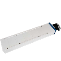
VP 710 Series
Vertical Tumble Stirrer
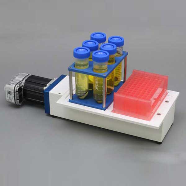
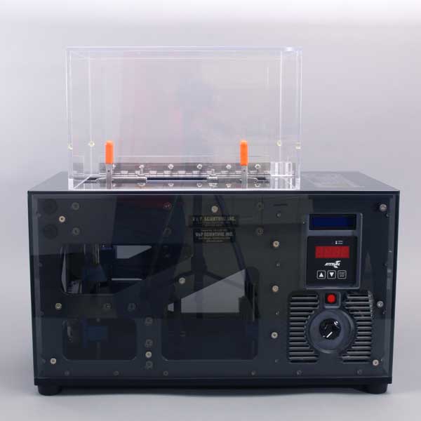
The Vertical Tumble Stirrer uses patented Magnetic Stir-Cylinder technology to mix large numbers of samples in microplates, racks of tubes, syringes, and small bottles (USA Patent #6,176,609).
Instead of spinning a magnetic stir bar about the horizontal plane like the standard horizontal magnetic flask stirrer, the Vertical Tumble Stirrer causes stir elements of all sizes and shapes to tumble vertically end-over-end inside each well or vessel. So each microplate well or tube in a rack, syringe, or small bottle receives the same vigorous mixing regardless of the position within the microplate or rack.
The Alligator Vertical Tumble Stirrer will stir all types of microplates of any volume or format. It will also stir V and U bottom microplates, PCR plates, micro-centrifuge tubes, test tubes, syringes, and small bottles, and specially designed Bubble Paddle reservoirs. Perhaps the best way to appreciate how the Vertical Tumble Stirrers function is to see all the videos above and below.
Mix the contents of any Microplate, Tube, Rack, Small Bottle, or Syringe.
- Process Parallel synthetic reactions
- Facilitates Micro-fermentation reactions
- Parallel Artificial Membrane system to evaluate absorption
- Mix and aerate cultures to increase yield
- Solubilize compounds dried in microplates
- Mix bread dough
- Quantitative measure of cytotoxicity of anticancer drugs and other agents
- High throughput solubility determination with application to the selection of compounds for fragment screening
- Parallel fed-batch cultivations in micro bioreactors
- High-throughput cocrystal slurry screening
- Solubility studies
- Adaptive Laboratory Evolution
- Growth Rate, Metabolite Production, and Final Biomass in a Tumble Stirred Culture Vessel
- Measurement of oxygen consumption by murine tissues in vitro
- Miniaturization of fermentations and chemical reactions
- Stirring chemical reactions to speed completion
- Simultaneous stirring at 3 different temperatures to determine optimum temperature for a reaction
- Heat and Stir to facilitate compound synthesis
- Rapid and efficient stirring of any format microplates, test tubes, vials, and syringes
- Thorough mixing of slurries, viscous solutions, and emulsions
- Thorough mixing of immiscible liquids
- Keep particulates in suspension
- Resuspend chemical libraries after storage
- Aeration of microbial cultures to increase DNA or protein yield
- Enables parallel synthetic development of processes
- Resuspend settled microorganisms
- Keep microorganisms suspended during gridding operations
- Break up filamentous organisms
- Dissolve solid compounds
- Resoluabilize dried extracts from large screening libraries
- Mix and immobilize reactions that use magnetic beads
- Large and Strong Magnetic Cylinders
- Allows use of Inexpensive Stir Elements
- High Throughput
- Stir 11,520 Wells at Once
- Heat (200°C) AND Stir
- Speeds Chemical Reactions
- Run Multiple Experiments in Parallel
- Flexible Orientation of Stir Deck and Heat Shields
- Easily Customizable
- Up to Three Temperature Zones
- Compatible with Most Robotic Liquid Handlers
- Stirs Bubble Paddle Reservoirs
- Set Exact RPM’s
- Enables Reproducible Results Day-to-Day
- Durable
- Stir Continuously for Years Without Maintenance
- Stir Viscous Solutions
- 6.6 Times More Viscous than Honey
Using large and the most powerful permanent magnets manufactured, we make many different models of Vertical Tumble Stirrers to fit the many varied applications and requirements of our customers. Requirements for heating and continuous stirring for a long period of time demand special Vertical Tumble Stirrers that are resistant to heat and with motors capable of working under high loads for extended periods.
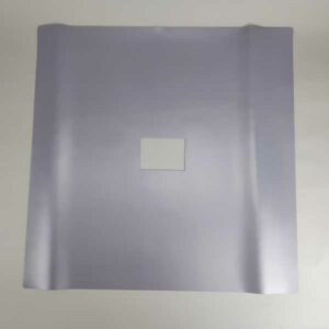
We make our Vertical Tumble Stirrers heat resistant using Mica. The Mica deck will accommodate three of our V&P heat blocks operating at 200C. Please check with our knowledgeable staff to help you make the appropriate selection for your application. Our specialty is flexibility- let us know if you have a custom application today!
We offer a large assortment of economical magnetic Stainless Steel Stir Elements from Stir StiXs to Discs to bars and dowels to fit into any well, tube, or syringe.
We also sell Alnico and Rare Earth Magnetic Stir Elements for more viscous solutions.
Check out the Stir Elements page for more information on coatings and dimensions.
- The Analyst-2012-Edwards
- Microplate Mixing Dr. John Comley 2007-2008
- Journal of Pharmacological and Tox.-2011-Al Samri
- Journal of Chromatography-2010-Alelyunas
- j03-ET&C (Permeability)
- j02-Anal Chem (K_PDMSw)
- j01-EST (PDMS-PAMPA)
- Intl. Journal of Pharmaceutics-2013-Hu
- International Journal of Pharmaceutics-2010-Kojima
- Fertility and Sterility-2009-Badawy
- Chemical Engineering Science-2009-van Leeuwen
- Bioorganic & Medicinal Chemistry-2008-Colclough
- Applied Microbiology and Biotechnology-2013-Vejrazka
- Appl Microbiol Biotechnol-2014-Aguirre
- Analytical Biochemistry-2008-Tao
- Adaptive Laboratory Evolution with Tumble Stirring – UCSD
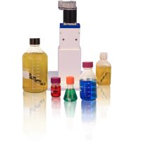
VP 708 Series
Lateral Tumble Stirrer
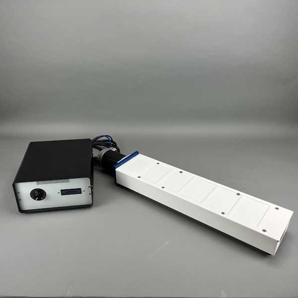
The Lateral Tumble Stirrer uses patented Magnetic Stir-Cylinder technology to mix large numbers of samples in microplates, racks of tubes, syringes, multiple large bottles, and carboys.
V&P Scientific, Inc. has invented and built the world’s first Lateral Tumble Stirrer (USA Patent #7,484,880, European Union Patent #1,736,235, and German Patent #60 2006 026 122.5).
Instead of tumbling a Stir Element in the vertical plane like our Vertical Tumble Stirrer, the Lateral Tumble Stirrer spins the stir elements by tumbling them laterally against a sidewall of the vessel. This spinning motion produces a vortex cone in the liquid and efficiently mixes the contents of the liquid. However, unlike the conventional horizontal stirrers which require a unique drive magnetic field under each vessel or well, the Lateral Vortex Tumble Stirrer because of its lateral wall tumbling action only requires one vertically placed drive magnetic cylinder to stir thousands of vessels or wells surrounding it.
The Lateral Tumble Stirrer causes stir elements of all sizes and shapes to tumble laterally and create a vortex cone inside each well or vessel. The Lateral Tumble Stirrer will stir all types of microplates (24, 48, 96, 384, and even 1536 wells, and tubes, multiple large bottles, and even carboys.
Mix Microplates, Deep Well Microplates, Racks of Tubes, Syringes, multiple large Bottles, or Carboys
- Large and Strong Magnetic Cylinders
- Allows use of Inexpensive Stir Elements
- High Throughput
- Stirs 4,608 Wells at Once
- Run Multiple Experiments in Parallel
- Set Exact RPM’s
- Enables Reproducible Results Day-to-Day
- Durable
- Stir Continuously for Years Without Maintenance
- Stir Viscous Solutions
- 6.6 Times More Viscous than Honey
- Can stir in any vessel regardless of the size or shape
- Can increase the aeration of microbial cultures
- CE compliant
- Available in 110 and 220 volt versions
Using large and the most powerful permanent magnets manufactured, we make 2 different models of Lateral Tumble Stirrers to fit the many varied applications and requirements of our customers. Requirements for a long run time demand motors that are capable of working under high loads for extended periods. Please check with our knowledgeable staff to help you make the appropriate selection for your application. Our specialty is flexibility- let us know if you have a custom application today
We offer a large assortment of economical magnetic Stainless Steel Stir Elements from Stir StiXs to bars and dowels to fit into any well, tube, syringe large bottle or carboy.
We also sell Alnico and Rare Earth Magnetic Stir Bars for more viscous solutions.
Check out the Stir Elements page for more information on coatings and dimensions.
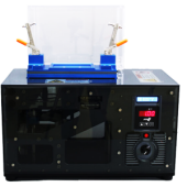
VP 707 Series
Levitation Stirrer
The Levitation Stirrer uses patented Magnetic Levitation technology to mix large numbers of samples in deep well microplates (48, 96 and 384 microplates) (US patent #6,357,907; EU patent #1064988).
Instead of tumbling a Stir Element in a vessel the Levitation Stirrer uses a very strong magnetic dipole field to levitate stainless steel balls in deep well microplates. After several levitation passes the contents of the well are mixed from top to bottom. However, unlike the conventional horizontal stirrers which require a unique drive magnetic field under each well, the Levitation Stirrer because of its levitation action only requires one large magnetic dipole field to mix up to 4,608 wells (twelve 384 deep well microplates).
The Levitation Stirrer was initially made for Celera Genomics in the race to sequence the human genome. Celera Genomics needed to suspend replicated Human DNA released from bacteria at the bottom of 384 deep well microplates so the DNA could be read by the sequencer. Celera Genomics called the Levitation Stirrer an “enabling technology”.
Other applications include mixing very viscous materials such as paint, toothpaste and lotions with biocides, flavorings, or coloring agents to determine the proper concentration to use. Being able to perform mixing experiments in microplates allows one the ability to test many variables at the same time.
- Large and Strong Magnetic Dipoles
- Allows use of Inexpensive Stir Elements (Ball Bearings)
- High Throughput
- Stir 4,608 Wells at Once
- Heat (to 37°C) Stir and aerate
- Culture bacterial and mammalian cells
- Run Multiple Experiments in Parallel
- Compatible with some Robotic Liquid Handlers
- Set Exact RPM’s
- Enables Reproducible Results Day-to-Day
- Durable
- Stir Continuously for Years Without Maintenance
- Stir Viscous Solutions
- 6 Times More Viscous than Honey
The Carousel style which stirrers 12 deep well microplates (48, 96 and 384 wells) on a carousel plate and passes the microplates between a large and powerful NdFeB dipole magnet to raise magnetic stainless steel balls in the microplate and dropping them by gravity when they leave the magnetic field.
The second style of Levitation Stirrer only moves one deep well microplate back and forth on a linear shuttle and thus in and out of a powerful NdFeB dipole magnetic field to raise the balls and using gravity to drop the balls as they leave the magnetic field.
The third style of Levitation Stirrer also only moves one deep well microplate at a time but it does it by raising and lowering the microplate vertically in a larger and more powerful NdFeB dipole magnetic field so the magnetic stainless steel balls are both lifted up by the magnetic field and pulled down by the magnetic field. This is a very important ability when mixing very viscous fluids such as paint, lotions and toothpaste.
We offer an assortment of economical magnetic Stainless Steel ball bearings of different diameters. We also offer these same ball bearings that are coated with parylene when iron ions may interfere with the assay results. We also offer one Stainless Steel ball bearing that is coated with PTFE and another ALNICO round stir ball that is coated with PTFE. Our Alnico Magnetic Stir Balls are used for more viscous solutions.
Check out the Stir Elements page for more information on coatings and dimensions.
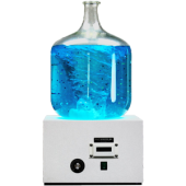
VP 706 Series
Large Conventional Horizontal Stirrer
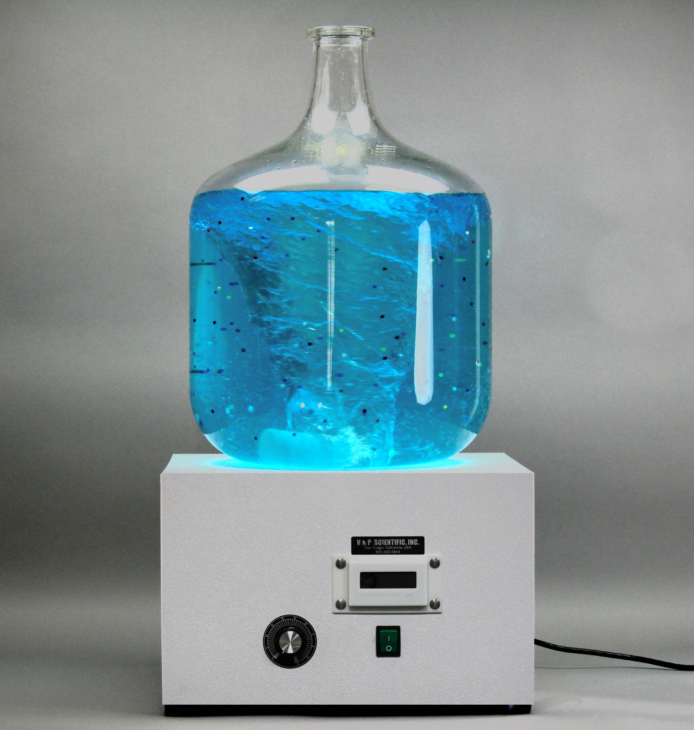
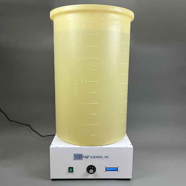
Our large conventional style stirrers are aimed at mixing industrial sized containers from carboys, barrels to 600 gallon containers. Our large NdFeB drive magnet is attached to Nema 34 quad stack servo motor and is capable to generating speeds of 1000 RPM.
Conventional Horizontal Magnetic Stirrers
The Conventional Horizontal Magnetic Stirrer technology has been around since 1944. This system uses a motor to spin a drive magnet whose moving magnetic field connects with the magnetic field of a stir bar causing the stir bar to spin on a horizontal plane in a vessel above the drive magnet. V&P Scientific has improved that basic system.
Secrets Behind V&P Scientific’s Stirrus Technology:
- The drive magnets in the V&P Scientific Stirrus machines use very large and very powerful (48 MGO) NdFeB rare earth magnets. These are much larger and more powerful than the Alnico magnets (8 MGO) used in conventional horizontal stirrers.
- This means that V&P Scientific Stirrus machines project their magnetic field farther and form a stronger attachment to the Stir elements thus allowing them to stir very viscous solutions.
- V&P Scientific stir elements are made with powerful (48 to 52 MGO) NdFeB Rare Earth magnets and V&P is the only company to offer a full line of NdFeB stir elements to accommodate every vessel size.
- V&P is also the only source for 48 and 52 MGO NdFeB Stir elements.
- The extremely strong magnetic coupling/attraction between the V&P Scientific Stirrus drive magnet and the stir element, enables stirring at high speed and in a viscous material.
- The motors in V&P Scientific Stirrus machines are very powerful and can maintain that power through both the low and the high speeds often required when mixing very viscous materials.
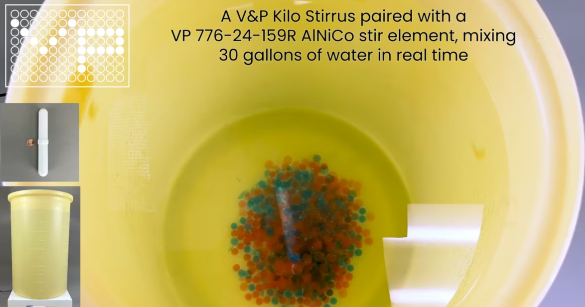
- Even liquids as viscous as 90% honey are easily stirred producing impressive vortex cones.
Applications of Conventional Magnetic (Horizontal) Stirring
- There are many applications for conventional magnetic stirring ranging from simply mixing two or more compounds together, or dissolving one compound into a liquid, or mixing to speed a chemical reaction.
- Many of the customers who are using our Stirrus Machines (VP 706 series) do so because they need to have the power to be able to mix very viscous liquids at both slow and high speeds.
- Another need is to be able to stir vessels as large as 600 gallons.
- Another capability of the Stirrus Machines arises from our ability to manufacture stir elements specifically made to couple strongly with the Stirrus’ drive magnetic field.
- We also make stir elements for our Stirrus Machines whose physical shape can be changed to match the application or shape of the vessel.
- One of the unusual applications is the use of Stirrus Machines to macerate chicken embryo tissue into single-cell preparations to seed large tissue culture bottles for vaccine production.
- Other customers have used the Stirrus Machines to mix slurries.
- Can stir large volumes of viscous material
- Can support the weight of large containers
- Can spin at high and low speed
- Drive Magnet design enhances coupling to Stir Element
The MidiStirrus is capable of stirring vessels up to carboy size vessels
The KiloStirrus is capable of stirring vessels up to 600 gallons in size.
We offer a large assortment of ALNICO, Samarium Cobalt and Neodymium Iron Boron Stir Elements from stir bars to H shapes and suspended stir elements to fit into any Carboy or large vessel. Check out the Stir Elements page for more information on ALNICO and Rare Earth Magnetic Stir Bars for more viscous solutions
Feedback for the Tumble Stirrers is this: enabling technology. I am now enabled to create reaction blocks and customize them to robotic systems with great ease. Why? The narrow deck height of the Tumble stirrers (even my larger strength units) combined with flexibility of alignment for the stirrers to the reaction vessels means I can use them almost anywhere.
The fact that I can use the same stirrer deck with any type/size of reactor simply by changing a mounting plate atop the stirrer deck gives me the kind of flexibility I require for parallel synthetic development of processes. That flexibility enables access to a wider range of projects (smaller scale) and a wider range of reaction conditions. I get more reactions per gram of starting material for evaluation of more diverse conditions, and I generate results faster because I run more of the experiments in parallel using the same amount of starting material. In one word, Tumble Stirring is enabling.
Oh, and the quality of agitation is fantastic for liquid-liquid mixes, slurries, or even oil suspensions.
Thanks again for this terrific product.
D____.”
— Investigator in Process R&D from a large pharmaceutical company
Discover the Perfect Mix for Your Experiments!
Unlock the full potential of your experiments with our versatile stirring and mixing products, designed for a wide range of applications. Take our quick Mixing Application Survey and let our expert team provide tailored advice to enhance your workflow efficiency. Find the right solution today and elevate your experiments to the next level!
Additional Offerings
OEM Cylinders
Contact us if you wish to integrate our patented stirring technology into your liquid handling system. We can tailor our magnets to fit your application.
Stirrer Accessories
We have many different accessories associated with our VP Stirrer Series. See the full complement below.
Playlist

Category
Container Used
Stirrer Products
Showing 1–12 of 23 results

