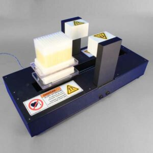
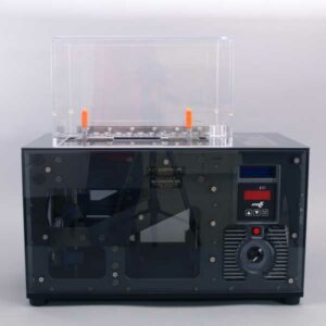
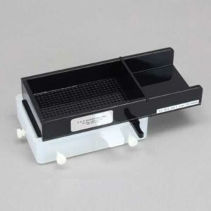
STIRRER, Levitation, Linear Shuttle Motion, Stirs One Deep Well Microplate, with Smart Motor and a Worm Gear Drive, 110 Volts, 60 Hz
Levitation Stirrer, Shuttle Style
STIRRER, Levitation, Linear Shuttle Motion, Stirs One Deep Well Microplate, with Smart Motor and a Worm Gear Drive, 110 Volts, 60 Hz
Container Used | Deep Well Microplates |
---|---|
Mode of Use | Benchtop |
Control Type | Manual Control |
Power Supply Input | 110V |
Frequency | 60 Hz |
CE Compliant | Yes |
Material | ABS |
Magnet Strength | 42MGO |
The V&P Scientific, Inc. Magnetic Levitation Stirrers (US patent #6,357,907; EU patent #1064988) were designed to stir the tall narrow columns of deep well 96 and Whatman Polyfiltronics deep well 384 microplates. As scientists have sought to increase the throughput of many processes they have turned to miniaturization and deep well microplates as a solution. However one of the problems of using deep well microplates is being able to adequately mix the well contents or resuspend particles in these tall narrow wells. Another problem was that of getting enough oxygen exchange through the relatively small surface area of the deep well microplates. We invented Magnetic Levitation Stirring as an efficient and inexpensive method to aerate and mix the contents of deep well microplates. The initial application was to resuspend human DNA which was amplified by replicating in bacteria in the bottom 384 deep well microplates. This levitation mixing facilitated the sequencing necessary for the Human Genome Project and was credited as being an “enabling technology” by Celera Genomics the company which was the first to successfully sequence 5 different humans. We were able to do this by simply raising and lowering stainless steel balls in all the wells by using a very strong horizontal magnetic field. This method produces a very vigorous stirring action that stimulates the growth of microorganisms, mixes with ease two or more liquids, and keeps particulates in suspension. Furthermore, if the media level in the wells is adjusted so the stir balls pass through the meniscus, aeration of microbial culture is increased and results in greater microbial yield as well as DNA and protein production.
The ability to stir extremely viscous solutions is a very useful characteristic of all the V&P Levitation Stirrers. Our Levitation Stirrers and Stir Balls are able to mix even solutions of 100,000 centistokes or 6.6 times more viscous than honey. A series of silicone viscosity standards were placed in the columns of a deep well microplate. The standard series viscosity was as follows: 100 cst, 1,000 cst, 5,000 cst, 10,000 cst, 12,500 cst, 30,000 cst, 60,000 cst and 100,000 cst.
For comparison 1 centistoke = 1.0760 x 10⁻⁵ sq. ft./sec.,
water = 1 cst
molasses ~ 2,500 cst
honey ~ 15,000 cst
Our VP 707B and VP 707C series Levitation stirrers can mix viscous solutions up to 30,000 cst while our VP 707E series Levitation stirrers are able to mix viscous solutions up to 100,000 cst because these stirrers use the magnet to also pull the stir balls down as well as to levitate them up. The VP 707B and VP 707C series Levitation Stirrers rely on gravity to pull the stir balls down.
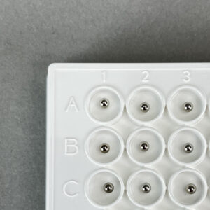
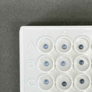
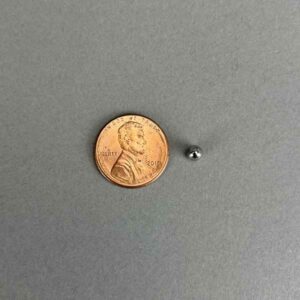
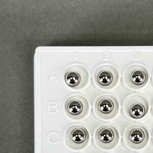
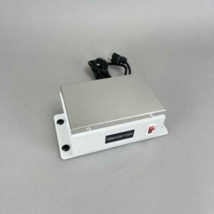
The Levitation Stir Balls are made from corrosion-resistant stainless steel and come in a variety of sizes to accommodate all 96 and 384 deep well microplates. The Levitation Stir Balls are also provided encapsulated in parylene for combinatorial chemical reactions and other reactions that may be sensitive to metal ions. We can make any Levitation Stir Ball into a Sterile version contained in a Pyrex bottle. Although the cost of the balls is low enough to discard them after one use, they can be recovered, washed, demagnetized, and used over and over. Each of the Levitation Stir Balls is tested for magnetic energy and only those that pass our stringent testing are accepted.
Dispensers for loading the balls into the wells are also available for each ball size. These dispensers can quickly and accurately place sterile or non-sterile balls into the wells. One of the advantages of stainless steel balls over permanent magnets is that the stainless steel may be demagnetized so they don’t “clump” in the dispensers as the permanent magnets do.
Removing the balls from the wells after they are used can be done as easily and as sterilely as your assay conditions dictate. If your assay is completed and all the liquid has been removed, you can invert the microplate and magnetically collect the balls as they fall out. If the liquid is still in the wells and you want to remove the balls and leave the liquid behind just use the VP 770 Magnetic Plate System for stir ball extraction.
Scientists can apply this unique methodology to many different areas that require the mixing of liquids or suspending particulates in the tall narrow wells of deep well microplates. The most cost-effective is the manual Magnetic Levitation Stirrer VP 707. With as few as 10 back-and-forth strokes the contents of the wells are mixed. This Stirrer functions to levitate the balls by sliding the microplate through a horizontal magnetic field and then pulls the balls down by passing over a vertical magnetic field. The VP 707 is ideally suited to stir combinatorial chemical reactions or other reactions where continuous stirring is not required. The manual VP 707 has a footprint of only 20 cm wide by 64 cm long and 16 cm tall. This stirrer will stir one deep well microplate at a time at up to 100 lifts/minute.
All Levitation Stirrers are equipped with microplate “hold down shoes” designed to fit the Polyfiltronic/Whatman 384 deep well blocks (Uni Plate 400 – 400 ul volume) and ABgene’s 96 deep well blocks (2.2 ml volume) #AB-0661. Both these deep well blocks have a broad flat flange on the bottom and no skirt. This feature allows easy capture of the plate and holds it securely in a strong magnetic field. Hold-down shoes for other manufacture’s microplates will be done on a custom basis.
We also have microplate “hold down shoes” for Seahorse BioScience’s 4 ml 96 well blocks to fit on the VP 707C Linear Levitation Shuttle. We have also made custom “hold down shoes” for Seahorse’s 4 ml 96 well blocks that fit on the VP 707B Carousel.
However, as a safety factor, we recommend that people with pacemakers keep at least 36″ or 91 cm from the Alligator Vertical Tumble Stirrers and the Vortex Lateral Tumble Stirrer. V&P does not make any claims in regard to the validity of the 5 gauss threshold for deactivating implanted medical devices. The 5 gauss magnetic field is a guideline to avoid risks associated with magnets and implanted medical devices such as pacemakers. For more information, please consult your physician. We try to position the magnet as close to the deck as possible given the constraints of the magnetic cylinders and deck design. Note the distance between the magnet surface and the surface of the deck varies for each magnetic tumble stirrer design and thus the gauss levels at the surface of the deck vary.
Pin | Description | nl Transferred | CV% | |
---|---|---|---|---|
0.229 mm diameter (FP9) | Total Pin | Uncoated | 7.41 | 2.4 |
Hydrophobic | 7.46 | 5.4 | ||
0.229 mm diameter (FP9) | Hanging Drop | Uncoated | N/A | N/A |
Hydrophobic | 2.09 | 3.8 | ||
0.457 mm diameter (FP1) | Total Pin | Uncoated | 33.48 | 3.2 |
Hydrophobic | 28.17 | 7.5 | ||
0.457 mm diameter (FP1) | Hanging Drop | Uncoated | 16.96 | 4.5 |
Hydrophobic | 8.51 | 0.8 | ||
0.787 mm diameter (FP3) | Total Pin | Uncoated | 87.32 | 3.9 |
Hydrophobic | 77.4 | 3.9 | ||
0.787 mm diameter (FP3) | Hanging Drop | Uncoated | 48.77 | 1.2 |
Hydrophobic | 43.05 | 9.4 | ||
1.19 mm diameter (VP 409 & VP 386) | Total Pin | Uncoated | 247.22 | 2.8 |
Hydrophobic | 192.67 | 2.6 | ||
1.19 mm diameter (VP 409 & VP 386) | Hanging Drop | Uncoated | 76.35 | 1.6 |
Hydrophobic | 108.4 | 2.8 | ||
1.58 mm diameter (VP 408 & VP 384) | Total Pin | Uncoated | 273.5 | 4.6 |
Hydrophobic | 259.25 | 3.1 | ||
1.58 mm diameter (VP 408 & VP 384) | Hanging Drop | Uncoated | 201.93 | 5 |
Hydrophobic | 170.04 | 7.5 |
Transfer Of Horseradish Peroxidase In Tris Buffered Saline With Pin Tools
Coating pins will reduce the total amount of liquid transferred and also reduce the amount of non-specific binding to the stainless-steel pins. If the substance you are transferring has high non-specific binding this will be an important factor in selecting your pins.
Pin | Description | nl Transferred | CV% | |
---|---|---|---|---|
0.229 mm diameter (FP9) | Total Pin | Uncoated | 7.41 | 2.4 |
Hydrophobic | 7.46 | 5.4 | ||
0.229 mm diameter (FP9) | Hanging Drop | Uncoated | N/A | N/A |
Hydrophobic | 2.09 | 3.8 | ||
0.457 mm diameter (FP1) | Total Pin | Uncoated | 33.48 | 3.2 |
Hydrophobic | 28.17 | 7.5 | ||
0.457 mm diameter (FP1) | Hanging Drop | Uncoated | 16.96 | 4.5 |
Hydrophobic | 8.51 | 0.8 | ||
0.787 mm diameter (FP3) | Total Pin | Uncoated | 87.32 | 3.9 |
Hydrophobic | 77.4 | 3.9 | ||
0.787 mm diameter (FP3) | Hanging Drop | Uncoated | 48.77 | 1.2 |
Hydrophobic | 43.05 | 9.4 | ||
1.19 mm diameter (VP 409 & VP 386) | Total Pin | Uncoated | 247.22 | 2.8 |
Hydrophobic | 192.67 | 2.6 | ||
1.19 mm diameter (VP 409 & VP 386) | Hanging Drop | Uncoated | 76.35 | 1.6 |
Hydrophobic | 108.4 | 2.8 | ||
1.58 mm diameter (VP 408 & VP 384) | Total Pin | Uncoated | 273.5 | 4.6 |
Hydrophobic | 259.25 | 3.1 | ||
1.58 mm diameter (VP 408 & VP 384) | Hanging Drop | Uncoated | 201.93 | 5 |
Hydrophobic | 170.04 | 7.5 |
Transfer Of Horseradish Peroxidase In Tris Buffered Saline With Pin Tools
Although the slots in the pin are a precise volume, the liquid that is transferred is usually more. The reason for this is due to the surface tension of the liquid causing the liquid in the slot to “bow out” thus increasing the volume of the liquid in the slot. If is important for you to transfer exactly a certain volume we can make custom slots to match the surface tension characteristics of your liquid
Solvent/Sample | Concentration | CV% | nl FITC Transferred | CV% | nl FITC Transferred |
---|---|---|---|---|---|
Uncoated | Uncoated | Hydrophobic Coated | Hydrophobic Coated | ||
DMSO (-) | 0 | 8.1 | 353.42 | 7.5 | 298.72 |
DMSO + DNA (mg/ml) | 0.5 | 6.6 | 497.21 | 6.6 | 435.86 |
0.25 | 9 | 432.49 | 4.1 | 391.93 | |
0.125 | 8.9 | 363.64 | 0.9 | 344.75 | |
0.0625 | 2.3 | 381.86 | 2 | 331.68 | |
0.0313 | 1.5 | 378.03 | 4.4 | 331.71 | |
0.0156 | 1.2 | 357.52 | 1.4 | 329.03 | |
Tris (-) | 0 | 4.9 | 577.31 | 7.2 | 493.53 |
Tris + DNA (mg/ml) | 0.5 | 4.5 | 540.53 | 1.1 | 477.5 |
0.25 | 4.6 | 518.21 | 6.1 | 456.75 | |
0.125 | 15.8 | 583.25 | 4.1 | 438.82 | |
0.0625 | 4.2 | 551.17 | 3.1 | 433.69 | |
0.0313 | 4.4 | 536.66 | 2.3 | 458.37 | |
0.0156 | 2.9 | 528.53 | 1.2 | 441.1 | |
Tris + BSA (%) | 4 | 5.4 | 462.13 | 11 | 409.27 |
1 | 4 | 452.86 | 2.7 | 426.58 | |
0.25 | 11.7 | 456.45 | 1.3 | 408.72 | |
0.0625 | 1.1 | 445.22 | 6.5 | 393.07 | |
0.0156 | 3.7 | 462.85 | 3.9 | 430.2 | |
0.0039 | 1.5 | 493.54 | 2.2 | 437.29 | |
0.001 | 2.9 | 504.25 | 0.7 | 475.96 |
1. Increasing the concentration of DNA (sheared salmon sperm) to .25 mg/ml significantly increases the volume of DMSO liquid transferred for both coated and uncoated FP3S500 Slot Pins.
2. Increasing the concentration of DNA does not significantly increase the volume of Tris buffer (aqueous) transferred by both coated and uncoated FP3S500 Slot Pins.
3. Increasing the concentration of BSA (Bovine Serum Albumin) significantly decreases the volume of Tris buffer transferred by both coated and uncoated FP3S500 Slot Pins.
4. Hydrophobic coated FP3S500 Slot Pins transferred less DMSO – DNA and less Tris DNA and less Tris BSA than the uncoated FP3S500 Slot Pins.
5. Both coated and uncoated FP3S500 pins transfer significantly more aqueous solution than DMSO.
Solvent/Sample | Concentration | CV% | nl FITC Transferred | CV% | nl FITC Transferred |
---|---|---|---|---|---|
Uncoated | Uncoated | Hydrophobic Coated | Hydrophobic Coated | ||
DMSO (-) | 0 | 4.2 | 49.38 | 2.1 | 49.31 |
DMSO + DNA (mg/ml) | 0.5 | 4.9 | 51.24 | 2.6 | 56.79 |
0.25 | 1.7 | 50.2 | 1.2 | 49.53 | |
0.125 | 1.5 | 51.27 | 2.3 | 49.77 | |
0.0625 | 2.2 | 49.34 | 4.1 | 48.19 | |
0.0313 | 1.2 | 49.03 | 0.2 | 50.23 | |
0.0156 | 2.4 | 45.9 | 1.4 | 46.64 | |
Tris (-) | 0 | 2.6 | 89.51 | 2.9 | 91.34 |
Tris + DNA (mg/ml) | 0.5 | 7 | 77.11 | 0.6 | 84.62 |
0.25 | 3.9 | 82.22 | 1.6 | 84.89 | |
0.125 | 3.9 | 85.42 | 1 | 85.08 | |
0.0625 | 1.5 | 85.36 | 2.8 | 85.03 | |
0.0313 | 2 | 84.52 | 3 | 88.19 | |
0.0156 | 2.6 | 82.92 | 2.8 | 83.2 |
1. In contrast to the FP3S500 data, increasing the concentration of DNA to .25 mg/ml does not significantly increase the volume of DMSO liquid transferred for both coated and uncoated FP1S50 Slot Pins.
2. Increasing the concentration of DNA does not significantly increase the volume of Tris buffer (aqueous) transferred by both coated and uncoated FP1S50 Slot Pins.
3. In contrast to the FP3S500 data, FP1S50 coated pins transferred about the same volume of DNA at all concentrations as did uncoated pins.
4. Both coated and uncoated FP1S50 pins transfer significantly more aqueous solution than DMSO.
5. The differences between the FP3S500 and the FP1S50 pin may be due to the different pin diameter’s effect on contact angle and therefore on the “wetting” of the pin. See the diagram on the link to / ah energy system.
Pin | Description | nl Transferred | CV% | |
---|---|---|---|---|
0.229 mm diameter (FP9) | Total Pin | Uncoated | 7.41 | 2.4 |
Hydrophobic | 7.46 | 5.4 | ||
0.229 mm diameter (FP9) | Hanging Drop | Uncoated | N/A | N/A |
Hydrophobic | 2.09 | 3.8 | ||
0.457 mm diameter (FP1) | Total Pin | Uncoated | 33.48 | 3.2 |
Hydrophobic | 28.17 | 7.5 | ||
0.457 mm diameter (FP1) | Hanging Drop | Uncoated | 16.96 | 4.5 |
Hydrophobic | 8.51 | 0.8 | ||
0.787 mm diameter (FP3) | Total Pin | Uncoated | 87.32 | 3.9 |
Hydrophobic | 77.4 | 3.9 | ||
0.787 mm diameter (FP3) | Hanging Drop | Uncoated | 48.77 | 1.2 |
Hydrophobic | 43.05 | 9.4 | ||
1.19 mm diameter (VP 409 & VP 386) | Total Pin | Uncoated | 247.22 | 2.8 |
Hydrophobic | 192.67 | 2.6 | ||
1.19 mm diameter (VP 409 & VP 386) | Hanging Drop | Uncoated | 76.35 | 1.6 |
Hydrophobic | 108.4 | 2.8 | ||
1.58 mm diameter (VP 408 & VP 384) | Total Pin | Uncoated | 273.5 | 4.6 |
Hydrophobic | 259.25 | 3.1 | ||
1.58 mm diameter (VP 408 & VP 384) | Hanging Drop | Uncoated | 201.93 | 5 |
Hydrophobic | 170.04 | 7.5 |
Hydrophobic coating pins will reduce the total amount of aqueous HRP liquid transferred and also reduce the amount of non-specific binding to the stainless-steel pins. If the substance you are transferring has high non-specific binding this will be an important factor in selecting your pins.
Pin diameter also has an effect on the degree of reduction of liquid transfer with hydrophobic coating as the smaller the diameter the less the reduction of transfer. This is most likely due to the curvature of the pin affecting the wetting contact angle
Pin | Description | nl Transferred | CV% | ||
---|---|---|---|---|---|
0.457 mm diameter (FP1) | 6 nl Slot | Total Pin* | Uncoated | 25.6 | 10.8 |
Hydrophobic | N/A | N/A | |||
10 nl Slot | Total Pin* | Uncoated | 23.36 | 6.1 | |
Hydrophobic | 25.85 | 6.9 | |||
50 nl Slot | Total Pin* | Uncoated | 67.83 | 2.5 | |
Hydrophobic | N/A | N/A | |||
0.787 mm diameter (FP3) | 100 nl Slot | Total Pin* | Uncoated | 180.32 | 7.2 |
Hydrophobic | 205.84 | 5.5 | |||
200 nl Slot | Total Pin* | Uncoated | 277.82 | 4.9 | |
Hydrophobic | 287.3 | 3.8 | |||
500 nl Slot | Total Pin* | Uncoated | 581.16 | 5.2 | |
Hydrophobic | 555.69 | 3 |
Hydrophobic coating pins will slightly increase the total amount of DMSO FITC liquid transferred.
Pin | Description | nl Transferred | CV% | |
---|---|---|---|---|
0.787 mm diameter (FP3) | 100 nl Slot Total Pin, Including Slot | Uncoated | 195.69 | 1.6 |
Hydrophobic | 170.2 | 2.9 | ||
0.787 mm diameter (FP3) | 100 nl Slot, Slot Only | Uncoated | 149.67 | 4.9 |
Hydrophobic | 129.61 | 7.6 | ||
0.787 mm diameter (FP3) | 200 nl Slot Total Pin, Including Slot | Uncoated | 269.77 | 1.9 |
Hydrophobic | 228.62 | 17.1 | ||
0.787 mm diameter (FP3) | 200 nl Slot, Slot Only | Uncoated | 237.52 | 8.9 |
Hydrophobic | 186.9 | 5.9 |
Although the slots in the pin are a precise volume, the liquid that is transferred is usually more because of the volume carried on the sides of the pins.
As seen with other aqueous data the amount transferred on hydrophobic coated Slot pins is less than on uncoated Solid or Slot pins. Thus Hydrophobic coating has the most effect on aqueous transfers.
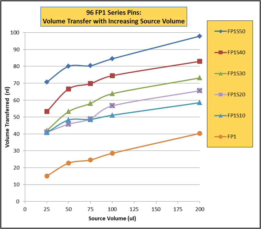
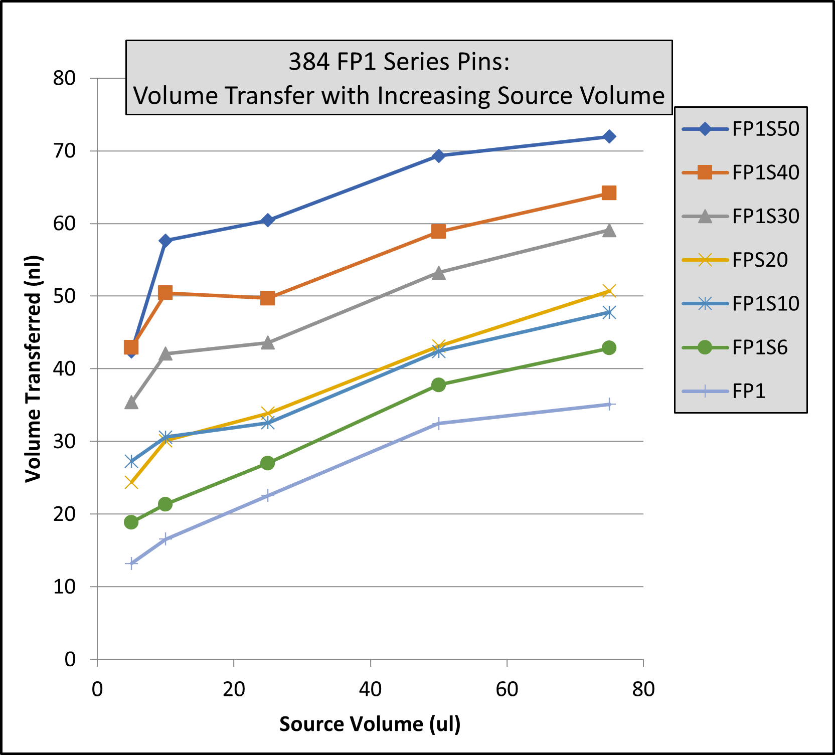
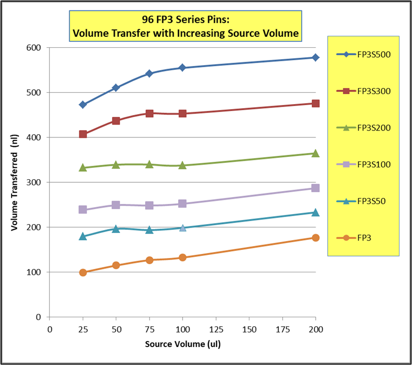
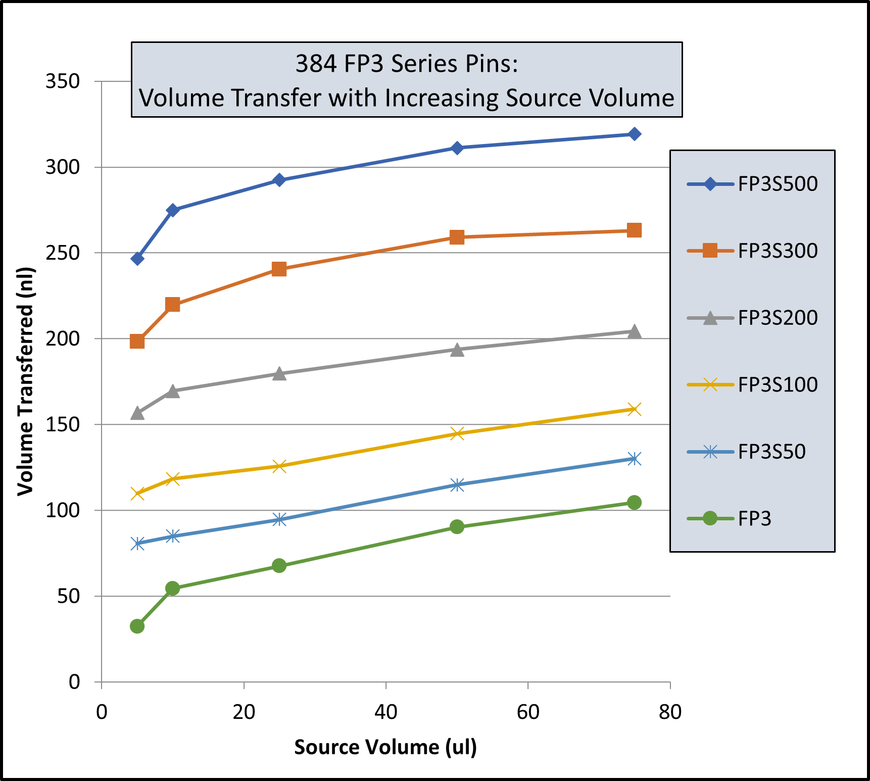
Note: Same volume (200ul for 96 Format and 74 ul for 384 Format) in recipient plates and same pin withdrawal speed for all pins. Changes to pin withdrawal speed or volume in the source plate can result in different volumes being transferred.
Transfer volumes should always be confirmed by customers for their assay conditions and automated system.
Pin Type | Pin Diameter(mm) | Shape | 96 Format Low Range(nL)² | 96 Format High Range(nL)² |
---|---|---|---|---|
FP9 | 0.229 | Solid | 13 | 39 |
FP8 | 0.356 | Solid | 15 | 37 |
FP1 | 0.457 | Solid | 22 | 61 |
FP1S6 | 0.457 | 6nL Slot | 34 | 67 |
FP1S10 | 0.457 | 10nL Slot | 39 | 74 |
FP1S50 | 0.457 | 50nL Slot | 90 | 124 |
FP3 | 0.787 | Solid | 93 | 213 |
FP3S100 | 0.787 | 100nL Slot | 213 | 334 |
FP3S200 | 0.787 | 200nL Slot | 311 | 449 |
FP3S500 | 0.787 | 500nL Slot | 515 | 671 |
FP4 | 0.914 | Solid | 126 | 289 |
Footnotes: (1) Delivery volume range is determined by speed of withdrawal from source liquid: Z-Speed Range = 1.5-30 mm/sec, slow speed = low volume delivery range, fast speed = high volume delivery range (2) 200ul source plate volume per well |
Pin Type | Pin Diameter(mm) | Shape | 96 Format Low Range(nL)² | 96 Format High Range(nL)² |
---|---|---|---|---|
FP9 | 0.229 | Solid | 13 | 38 |
FP8 | 0.356 | Solid | ||
FP1 | 0.457 | Solid | 23 | 60 |
FP1S6 | 0.457 | 6nL Slot | 33 | 67 |
FP1S10 | 0.457 | 10nL Slot | 40 | 75 |
FP1S50 | 0.457 | 50nL Slot | 86 | 119 |
FP3 | 0.787 | Solid | 76 | 209 |
FP3S100 | 0.787 | 100nL Slot | 188 | 324 |
FP3S200 | 0.787 | 200nL Slot | 288 | 436 |
FP3S500 | 0.787 | 500nL Slot | 473 | 649 |
FP4 | 0.914 | Solid | ||
Footnotes: (1) Delivery volume range is determined by speed of withdrawal from source liquid: Z-Speed Range = 1.5-30 mm/sec, slow speed = low volume delivery range, fast speed = high volume delivery range (2) 200ul source plate volume per well |
Pin Type | Pin Diameter(mm) | Shape | Low Range(nL)² | High Range(nL)² |
---|---|---|---|---|
FP | 1.58 | Solid Pointed | 175 | 594 |
FPS.5 | 1.58 | 500nL Slot | 524 | 962 |
FPS | 1.58 | 1000nL Slot | 1056 | 1476 |
FPS2 | 1.58 | 2000nL Slot | 1739 | 2174 |
FPS5 | 1.58 | 5000nL Slot | 5150 | 4953 |
FP6 | 1.58 | Solid Flat | 465 | 960 |
FP6S.5 | 1.58 | 500nL Slot | 934 | 1445 |
FP6S | 1.58 | 1000nL Slot | 1396 | 1930 |
FP6S2 | 1.58 | 2000nL Slot | 2072 | 2637 |
FP6S5 | 1.58 | 5000nL Slot | 4820 | 4693 |
Footnotes:(1) Delivery volume range is determined by speed of withdrawal from source liquid: Z-Speed Range = 1.5-30 mm/sec, slow speed = low volume delivery range, fast speed = high volume delivery range (2) 200ul source plate volume per well for 96 Format and 75ul source plate volume per well for 384 Format |
Pin Type | Pin Diameter(mm) | Shape | 96 Format Low Range(nL)² | 96 Format High Range(nL)² | 384 Format Low Range(nL)³ | 384 Format High Range(nL)³ |
---|---|---|---|---|---|---|
FP9 | 0.229 | Solid | 4 | 10 | 3 | 8 |
FP8 | 0.35 | Solid | 13 | 26 | 6 | 18 |
FP1 | 0.457 | Solid | 18 | 43 | 11 | 31 |
FP1S6 | 0.457 | 6nL Slot | 24 | 49 | 15 | 34 |
FP1S10 | 0.457 | 10nL Slot | 30 | 54 | 21 | 40 |
FP1S20 | 0.457 | 20nL Slot | 37 | 61 | 27 | 46 |
FP1S30 | 0.457 | 30nL Slot | 46 | 68 | 35 | 54 |
FP1S40 | 0.457 | 40nL Slot | 57 | 78 | 45 | 63 |
FP1S50 | 0.457 | 50nL Slot | 70 | 90 | 56 | 75 |
FP3 | 0.787 | Solid | 67 | 139 | 29 | 79 |
FP4 | 0.91 | Solid | 94 | 197 | 34 | 98 |
FP3S100 | 0.787 | 100nL Slot | 175 | 241 | 114 | 163 |
FP3S200 | 0.787 | 200nL Slot | 280 | 332 | 203 | 250 |
FP3S500 | 0.787 | 500nL Slot | 535 | 559 | 427 | 464 |
FP4S1000 | 0.91 | 1000nL Slot | 940 | 1011 | 704 | 800 |
FP4S2000 | 0.91 | 2000nL Slot | 1518 | 1608 | 1277 | 1362 |
Footnotes: (1) Delivery volume range is determined by speed of withdrawal from source liquid: Z-Speed Range = 1.5-30 mm/sec, slow speed = low volume delivery range, fast speed = high volume delivery range (2) 200ul source plate volume per well (3) 75ul source plate volume per well |
Pin Type | Pin Diameter (mm) | Shape | 96 Format Low Range(nL)² | 96 Format High Range(nL)² | 384 Format Low Range(nL)³ | 384 Format High Range(nL)³ |
---|---|---|---|---|---|---|
FP9H | 0.229 | Solid | 4 | 10 | 3 | 8 |
FP8H | 0.35 | Solid | 9 | 24 | 6 | 17 |
FP1H | 0.457 | Solid | 15 | 39 | 9 | 27 |
FP1S6H | 0.457 | 6nL Slot | 23 | 49 | 14 | 32 |
FP1S10H | 0.457 | 10nL Slot | 29 | 53 | 20 | 38 |
FP1S20H | 0.457 | 20nL Slot | 35 | 59 | 26 | 43 |
FP1S30H | 0.457 | 30nL Slot | 47 | 69 | 35 | 53 |
FP1S40H | 0.457 | 40nL Slot | 54 | 75 | 41 | 58 |
FP1S50H | 0.457 | 50nL Slot | 69 | 90 | 57 | 73 |
FP3H | 0.787 | Solid | 67 | 134 | 27 | 76 |
FP4H | 0.91 | Solid | 95 | 189 | 32 | 102 |
FP3S100H | 0.787 | 100nL Slot | 170 | 227 | 108 | 164 |
FP3S200H | 0.787 | 200nL Slot | 266 | 320 | 190 | 239 |
FP3S500H | 0.787 | 500nL Slot | 520 | 542 | 416 | 456 |
FP4S1000H | 0.91 | 1000nL Slot | 932 | 1000 | 741 | 805 |
FP4S2000H | 0.91 | 2000nL Slot | 1571 | 1638 | 1351 | 1423 |
Footnotes: (1) Delivery volume range is determined by speed of withdrawal from source liquid: Z-Speed Range = 1.5-30 mm/sec, slow speed = low volume delivery range, fast speed = high volume delivery range (2) 200ul source plate volume per well (3) 75ul source plate volume per well |
Pin Type | Diameter (mm) | Shape | 96 Format Low Range(nL)² | 96 Format High Range(nL)² | 384 Format Low Range(nL)³ | 384 Format High Range(nL)³ |
---|---|---|---|---|---|---|
FP | 1.58 | Solid Pointed | 147 | 411 | 168 | 395 |
FPS.5 | 1.58 | 500nL Slot | 442 | 704 | 631 | 843 |
FPS | 1.58 | 1000nL Slot | 893 | 1130 | 1343 | 1498 |
FPS2 | 1.58 | 2000nL Slot | 1911 | 2038 | 2607 | 2767 |
FPS5 | 1.58 | 5000nL Slot | 3908 | 4296 | 5180 | 5253 |
FP6 | 1.58 | Solid Flat | 323 | 674 | 154 | 398 |
FP6S.5 | 1.58 | 500nL Slot | 734 | 1042 | 855 | 1053 |
FP6S | 1.58 | 1000nL Slot | 1210 | 1500 | 1638 | 1717 |
FP6S2 | 1.58 | 2000nL Slot | 2299 | 2384 | 2787 | 3068 |
FP6S5 | 1.58 | 5000nL Slot | 4329 | 4656 | 5237 | 5245 |
Footnotes:(1) Delivery volume range is determined by speed of withdrawal from source liquid: Z-Speed Range = 1.5-30 mm/sec, slow speed = low volume delivery range, fast speed = high volume delivery range (2) 200ul source plate volume per well (3) 75ul source plate volume per well |